RL251
THRU
RL257
2.5 Amp
Silicon Rectifier
50 to 1000 Volts
Features
∑
Low Cost
∑
Low Leakage
∑
Low Forward Voltage Drop
∑
High Current Capability
Maximum Ratings
∑
Operating Temperature: -55
∞
C to +150
∞
C
∑
Storage Temperature: -55
∞
C to +150
∞
C
∑
Typical Thermal Resistance (R
JA
) 35
∞
C/W
MCC
Catalog
Number
Device
Marking
Maximum
Recurrent
Peak Reverse
Voltage
Maximum
RMS
Voltage
Maximum
DC
Blocking
Voltage
RL251
---
50V
35V
50V
RL252
---
100V
70V
100V
RL253 --- 200V 140V 200V
RL254
---
400V
280V
400V
RL255
---
600V
420V
600V
RL256
---
800V
560V
800V
RL257
---
1000V
700V
1000V
Electrical Characteristics @ 25
∞
C Unless Otherwise Specified
Average Forward
Current
I
F(AV)
2.5 A
T
A
= 75
∞
C
Peak Forward Surge
Current
I
FSM
150A
8.3ms, half sine
Maximum
Instantaneous
Forward Voltage
V
F
1.0V
I
FM
= 2.5A;
T
A
= 25
∞
C
Maximum DC
Reverse Current At
Rated DC Blocking
Voltage
I
R
5.0
µ
A
50
µ
A
T
A
= 25
∞
C
T
A
= 100
∞
C
Typical Junction
Capacitance
C
J
35pF
Measured at
1.0MHz, V
R
=4.0V
*Pulse Test: Pulse Width 300
µ
sec, Duty Cycle 1%
R-3
DIMENSIONS
INCHES
MM
DIM
MIN
MAX
MIN
MAX
NOTE
A
---
.160
---
4.10
B
---
.160
---
4.10
C
.040
.042
1.01
1.07
D
1.000
---
25.40
---
A
B
D
D
C
Cathode Mark
www.
mccsemi
.com
omponents
21201 Itasca Street Chatsworth
!"#
$
% !"#
M C C
RL251 thru RL257
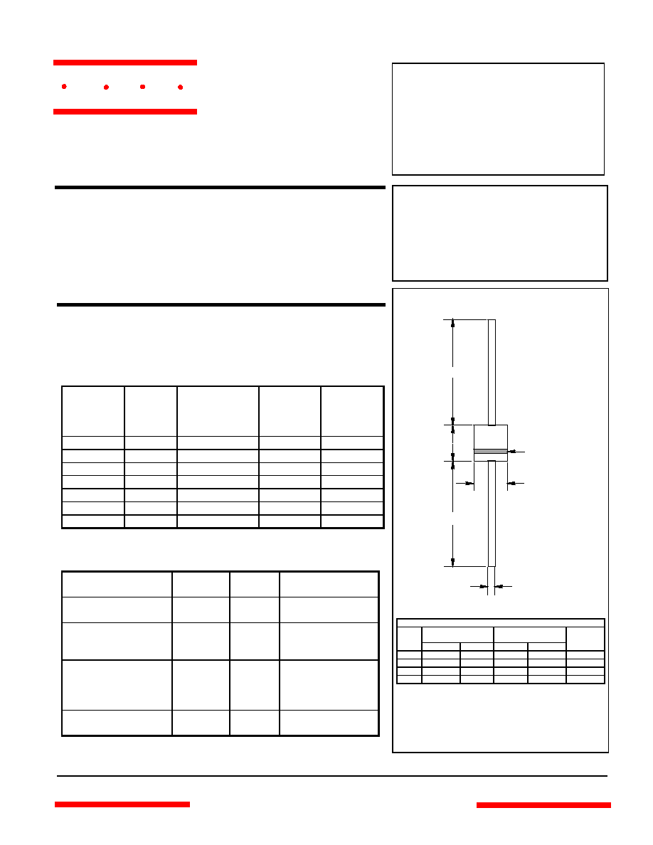
Average Forward Rectified Current - Amperes
versus
Ambient Temperature -
∞
C
Figure 2
Forward Derating Curve
0
175
50
75
100
125
0
.5
1.0
1.5
Single Phase, Half Wave
60Hz Resistive or Inductive Load
Amps
∞
C
150
2.0
2.5
3.0
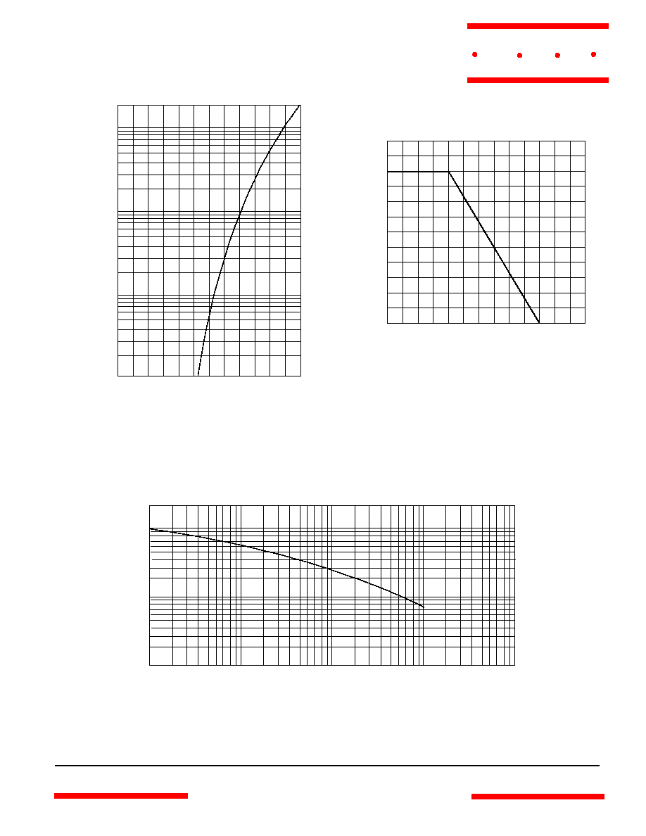
Junction Capacitance - pF
versus
Reverse Voltage - Volts
Instantaneous Forward Current - Amperes
versus
Instantaneous Forward Voltage - Volts
Figure 1
Typical Forward Characteristics
4
6
20
10
Amps
.2
.4
.6
.8
1.0
1.2
.01
.02
.04
.06
.1
.2
.4
.6
1
2
25
∞
C
Volts
Figure 3
Junction Capacitance
.1
.2
1
.4
2
10
20
40
4
100 200
1
2
6
10
20
100
pF
Volts
60
40
4
400
1000
T
J
=25
∞
C
www.
mccsemi
.com
M C C
RL251 thru RL257
Figure 4
Typical Reverse Characteristics
Volts
.4
.6
2
1
Amps
20
120
40
60
80
100
.001
.002
.00
4
.006
.01
.02
.04
.06
.1
.2
4
6
10
140
T
J
=25
∞
C
T
J
=100
∞
C
1
100
4
0
30
60
90
8
Figure 5
Peak Forward Surge Current
Peak Forward Surge Current - Amperes
versus
Number Of Cycles At 60Hz - Cycles
Amps
Cycles
2
6
10 20
60 80
40
120
150
180
Instantaneous Reverse Current - Amps
versus
Percent Of Rated Peak Reverse Voltage - Volts
www.
mccsemi
.com
M C C