RS401L
THRU
RS407L
Bridge Rectifier
50 to 1000 Volts
Features
∑
Low Leakage
∑
Low Forward Voltage
∑
Any Mounting Position
∑
Silver Plated Copper Leads
∑
Surge Overload Rating Of 200 Amps
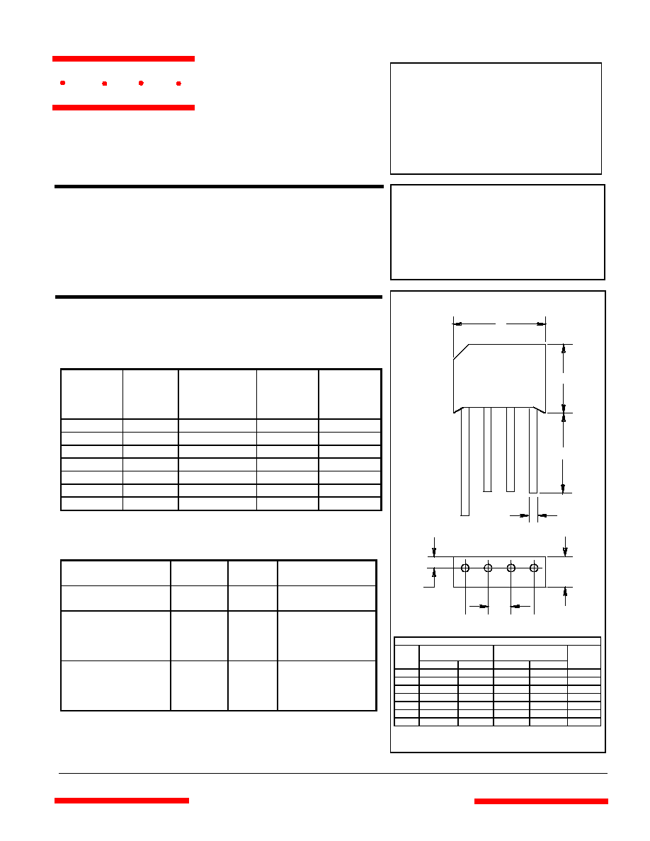
DIMENSIONS
INCHES
MM
DIM
MIN
MAX
MIN
MAX
NOTE
A .728 .768 18.50 19.50
B .600 .640 15.20 16.30
C .750 --- 19.00 ---
D .236 .256 6.00 6.50
E .180 .220 4.60 5.60
G ------ .083 ------ 2.10
Maximum Ratings
∑
Operating Temperature: -55
∞
C to +125
∞
C
∑
Storage Temperature: -55
∞
C to +150
∞
C
MCC
Catalog
Number
Device
Marking
Maximum
Recurrent
Peak Reverse
Voltage
Maximum
RMS
Voltage
Maximum
DC
Blocking
Voltage
RS401L RS401L
50V 35V 50V
RS402L RS402L
100V 70V 100V
RS403L RS403L
200V 140V 200V
RS404L RS404L
400V 280V 400V
RS405L RS405L
600V 420V 600V
RS406L RS406L
800V 560V 800V
RS407L RS407L
1000V 700V 1000V
Electrical Characteristics @ 25
∞
C Unless Otherwise Specified
Average Forward
Current
I
F(AV)
4.0A T
A
= 50
∞
C
Peak Forward Surge
Current
I
FSM
200A
8.3ms, half sine
Maximum Forward
Voltage Drop Per
Element
V
F
1.1V I
FM
= 3.0A;
T
J
= 25
∞
C
Maximum DC
Reverse Current At
Rated DC Blocking
Voltage
I
R
10
µ
A
1.0mA
T
J
= 25
∞
C
T
J
= 100
∞
C
*Pulse test: Pulse width 300
µ
sec, Duty cycle 1%
A
B
C
H
G
D
E
AC
+
-
H .048 .052 1.20 1.30
4 Amp Single Phase
www
.
mccsemi
.com
RS - 4L
omponents
21201 Itasca Street Chatsworth
!"#
$
% !"#
M C C
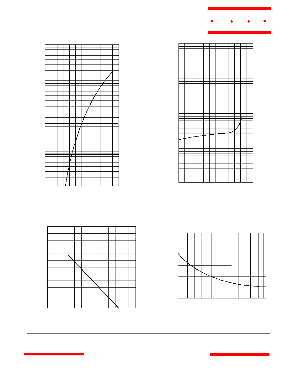
RS401L thru RS407L
Instantaneous Reverse Leakage Current - MicroAmperes
versus
Percent Of Rated Peak Reverse Voltage - Volts
Average Forward Rectified Current - Amperes
versus
Ambient Temperature -
∞
C
Figure 3
Forward Derating Curve
40
60
100
120
140
20
0
1
2
3
Single Phase, Half Wave
60Hz Resistive or Inductive Load
Amps
∞
C
80
4
5
6
1
100
4
0
50
100
150
8
Figure 4
Peak Forward Surge Current
Peak Forward Surge Current - Amperes
versus
Number Of Cycles At 60Hz - Cycles
Amps
Cycles
2
6
10
20
60 80
40
00
200
250
300
Instantaneous Forward Current - Amperes
versus
Instantaneous Forward Voltage - Volts
Figure 1
Typical Forward Characteristics
Volts
4
6
20
10
Amps
.2
1.2
.4
.6
.8
1.0
.01
.02
.04
.06
.1
.2
.4
.6
1
2
25
∞
C
40
60
100
1.4
Figure 2
Typical Reverse Characteristics
Volts
.4
.6
2
1
µ
Amps
20
120
40
60
80
100
.001
.002
.00
4
.006
.01
.02
.04
.06
.1
.2
4
6
10
140
T
J
=25
∞
C
www.
mccsemi
.com
M C C