SK52
THRU
SK510
5 Amp Schottky
Rectifier
20 to 100 Volts
Features
∑
For Surface Mount Applications
∑
Extremely Low Thermal Resistance
∑
Easy Pick And Place
∑
High Temp Soldering: 250
O
C for 10 Seconds At Terminals\
∑
High Current Capability With Low Forward Voltage
Maximum Ratings
∑
Operating Temperature: -55
O
C to +150
O
C
∑
Storage Temperature: -55
O
C to +150
O
C
∑
Maximum Thermal Resistance; 18
O
C/W Junction To Lead
MCC
Part
Number
Device
Marking
Maximum
Recurrent
Peak Reverse
Voltage
Maximum
RMS
Voltage
Maximum
DC
Blocking
Voltage
SK52
SK52
20V
14V
20V
SK53
SK53
30V
21V
30V
SK54
SK54
40V
28V
40V
SK545
SK545
45V
31.5V
45V
SK55
SK55
50V
35V
50V
SK56
SK56
60V
42V
60V
SK58
SK58
80V
56V
80V
SK510
SK510
100V
70V
100V
Electrical Characteristics @ 25
O
C Unless Otherwise Specified
Average Forward
Current
I
F(AV)
5.0A
T
J
= 120
∞
C
Peak Forward Surge
Current
I
FSM
150A
8.3ms, half sine
Maximum
Instantaneous
Forward Voltage
S
K52- 545
S
K55- 56
S
K58- 510
V
F
.55V
.75V
.85V
I
FM
= 5.0A;
T
J
= 25
O
C*
Maximum DC
Reverse Current At
Rated DC Blocking
Voltage
I
R
1.0mA
20mA
T
J
= 25
O
C
T
J
= 100
O
C
Typical Junction
Capacitance
C
J
200pF Measured at
1.0MHz, V
R
=4.0V
*Pulse test: Pulse width 200 usec, Duty cycle 2%
omponents
21201 Itasca Street Chatsworth
!"#
$
% !"#
M C C
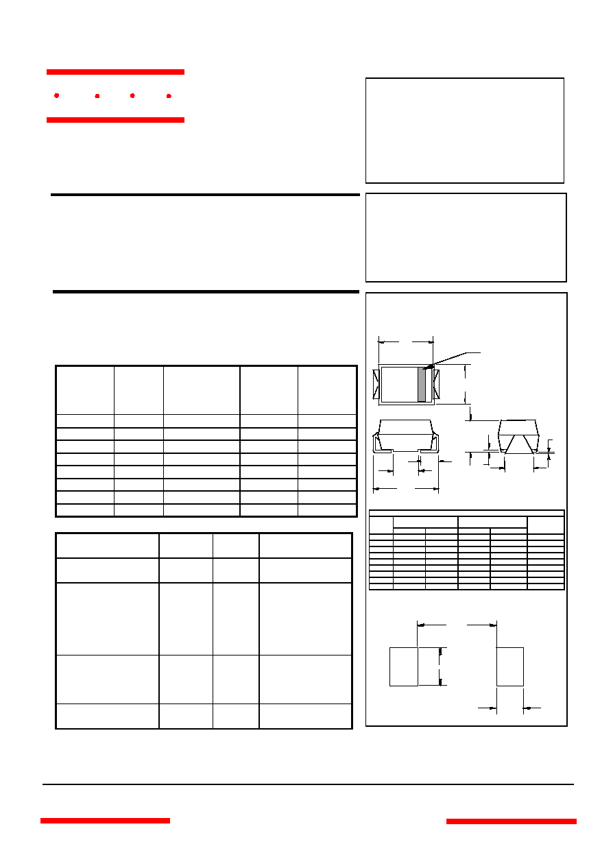
DO-214AB
(SMCJ) (Round Lead)
0.070"
0.190"
0.200"
SUGGESTED SOLDER
PAD LAYOUT
H
J
E
F
G
A
B
D
C
Cathode Band
DIMENSIONS
INCHES
MM
DIM
MIN
MAX
MIN
MAX
NOTE
A .200 .214 5.08 5.43
B .177 .203 4.70 5.30
C .002 .005 .05 .13
D
---
.02
---
.51
E .053 .067 1.35 1.70
F
.168
.179
4.27 4.55
G .320 .330 8.13 8.38
H
.239
.243
6.08
6.18
J .234 .240 5.95 6.10
www.
mccsemi
.com
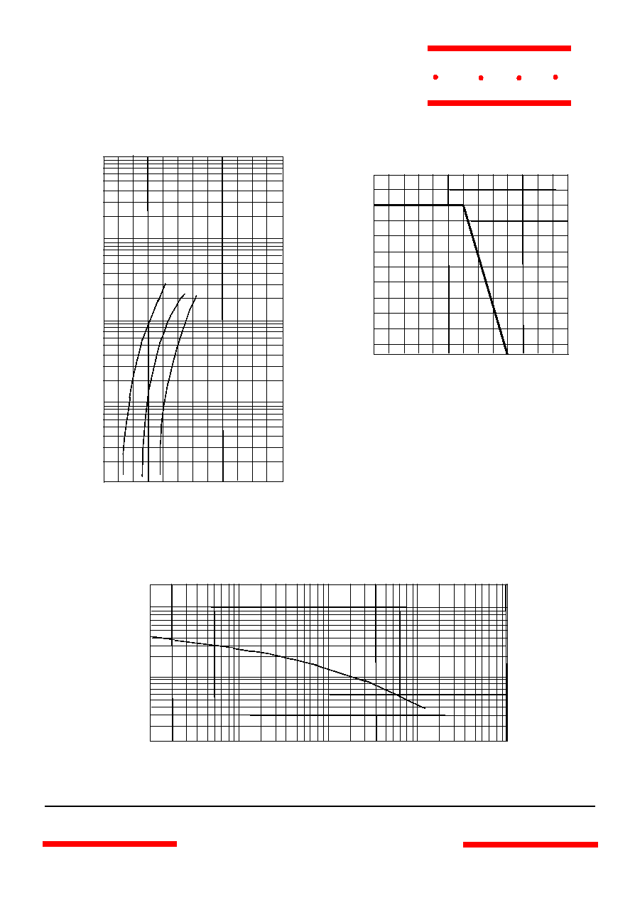
Average Forward Rectified Curre nt - Amperes
versus
Ambient Temperature -
∞
C
Figure 2
Forward Derating Curve
60 80
120
140
160
180
0
1
2
3
Single Phase, Half Wave
60Hz Resistive or Inductive Load
Amps
∞
C
100
4
5
6
Figure 3
Junction Capacitance
.1
.2
1
.4
2
10
20
40
4
100
200
10
20
60
100
200
100
0
pF
Volts
600
400
40
400
1000
T
J
=25
∞
C
www.
mccsemi
.com
M C C
SK52 thru SK510
Junction Capacitance - pF
versus
Reverse Voltage - Volts
Figure 1
Typical Forward Characteristics
Instantaneous Forward Current - Amperes versus
Instantaneous Forward Voltage - Volts
Volts
40
60
200
100
Amps
.2
1.2
.4
.6
.8
1.0
.1
.2
.4
.6
1
2
4
6
10
20
25
O
C
400
600
100
1.4
SK52-SK545
SK58-SK510
SK55-SK56
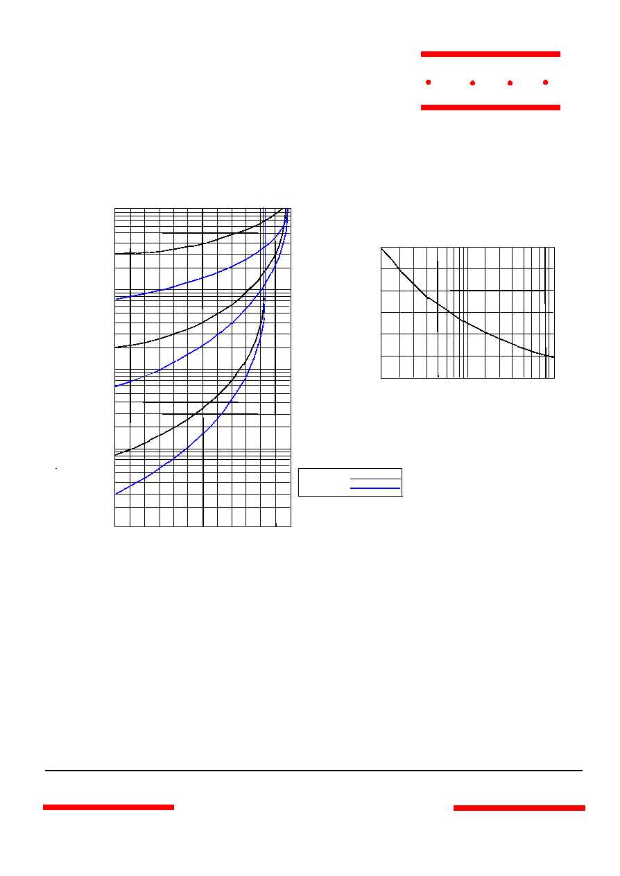
Figure 4
Typical Reverse Characteristics
Instantaneous Reverse Leakage Current - MicroAmperes
versus
Percent Of Rated Peak Reverse Voltage - Volts
Volts
.4
.6
2
1
µ
Amps
20
120
40
60
80
100
.001
.002
.004
.006
.01
.02
.04
.06
.1
.2
25
∞
C
4
6
10
140
1
100
4
0
25
50
75
8
Figure 5
Peak Forward Surge Current
Peak Forward Surge Current - Amperes
versus
Number Of Cycles At 60Hz - Cycles
Amps
Cycles
2
6
10
20
60
80
40
100
125
150
SK52 -SK545
SK55 -SK510
www.
mccsemi
.com
M C C
SK52 thru SK510