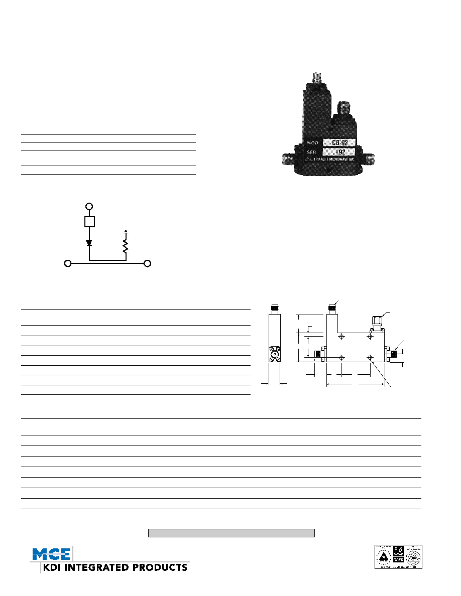
LOW LEVEL
DETECTORS, DIRECTIONAL SERIES CD
0.5-18 GHz
MECHANICAL OUTLINES
A B C D E F
Model No. in[mm] in[mm] in[mm] in[mm] in[mm] in[mm]
CD-22 3.25[82,55] 1.13[28,70] 1.800[45,7] 0.925[23,50] 0.73[18,54] 0.10[2,5]
CD-25 1.85[46,99] 1.13[28,70] 0.650[16,51] 0.925[23,50] 0.60[15,2] 0.10[2,5]
CD-32 1.20[30,48] 1.13[28,70] ≠≠ 0.925[23,50] 0.60[15,2] 0.10[2,5]
CD-62 1.00[25,4] 1.25[31,75] 0.475[12,06] __ 0.42[10,67] 0.68[17,27]
CD-82 1.00[25,4] 1.25[31,75] 0.475[12,06] ≠≠ 0.40[10,2] 0.68[17,27]
CD-84 1.00[25,4] 1.00[25,4] ≠≠ 0.800[20,3] 0.50[12,7] 0.10[2,5]
CD-92 1.00[25,4] 1.00[25,4] ≠≠ 0.800[20,3] 0.50[12,7] 0.10[2,5]
GENERAL INFORMATION
The Series CD Directional Directors are directional couplers with inte-
gral detectors. They are used for monitoring power without disturbing
the main line power flow. Series CD are low level devices using high
sensitivity detector diodes and high directivity couplers. They are
octave band units, but can be custom tuned to any narrow frequency
band in order to achieve flatter response.
GENERAL SPECIFICATIONS
Frequency Range: 0.5 to 18.0 GHz
RF Impedance: 50 Ohms
Temperature Information: Operating temperature from ≠55∞C to
+85∞C
Connectors: SMA
ELECTRICAL PERFORMANCE
Frequency (4) Minimum Maximum Insertion (2) Maximum Flatness Over (3) Detector Output Output Polarity
Model No. Range, GHz Directivity, dB Loss, dB VSWR Freq. Range, dB at 10mW Input* mV Note 1
CD-22 0.5-1.0 25 0.7 1.20 ±.75 125 neg.
CD-25 1.0-2.0 20 0.8 1.20 ±.75 125 neg.
CD-32 2.0-4.0 20 0.8 1.25 ±.75 125 neg.
CD-62 4.0-8.0 18 0.8 1.25 ±.75 100 neg.
CD-82 7.0-12.4 17 0.9 1.30 ±.75 75 neg.
CD-84 8.0-16.0 15 1.0 1.45 ±1.0 50 neg.
CD-92 12.0-18.0 14 1.0 1.50 ±1.0 50 neg.
*Across a 1,000 OHM load
DET. OUT
L.P. FILTER
RF OUT
RF IN
0.60[15,2]
MAX F
B D
0.50
[12,7]
0.38[9,7]
TYP.
E C
A
IN OUT
DET
OUT
SMA FEMALE
TYP.
0.25[6,4]
TYP.
0.093[2,36] DIA. THRU
MOUNTING HOLES
TERM
SMC
Notes:
1. Standard units are supplied with negative DC output. However, if positive output is
desired, place suffix P after the model number, e.g., CD-82-P
2. Insertion loss includes coupled loss (10 dB coupler).
3. Improved flatness specs are available on request.
4. If a narrow frequency bandwidth is required KDI/Triangle can supply a unit that is
electrically optimized for that bandwidth. Mechanical dimensions will remain the
same as the standard unit, and the price will generally be lower. Specify the fre-
quency range when ordering a narrow bandwidth model and a special part num-
ber will be assigned.
5. A 50 ohm termination is supplied on each unit delivered. Power rating is 1.0 watt
at +25∞C.
11-5-02
KEY: Inches[Millimeters] .XX ±.03 .XXX ±.010 [.X ±0.8 .XX ±0.25]
60 South Jefferson Road, Whippany, NJ 07981
Tel: 973-887-8100 ∑ Fax: 973-884-0445
email: sales@mcekdi-integrated.com
See us on the web @ www.mcekdi-integrated.com