
MODELS
DCF-A01, DCF-A02
CDMA/GSM Filter Combiner
TECHNICAL BULLETIN
60 South Jefferson Road, Whippany, NJ 07981
Tel: 973-887-5700 Fax: 973-884-4545 www.mcekdi-integrated.com
sales@kditriangle.com
1
3/9/02
This unit is designed for CDMA and GSM applications
where it is used to combine high power transmitter signals
to a common antenna port. Our combiner series offers sub-
stantially smaller size, improved insertion loss and other
RF performance that is superior to competing designs.
o Cavity Low Loss Diplexer Design
o High Input Port Isolation
o High Power Handling
o Custom Designs & Configurations available
upon request
DCF-A01
DCF-A02
Parameters
CDMA
GSM
CDMA
GSM
Frequency Range
824 - 880 MHz
909 - 960 MHz
824 - 880 MHz
909 - 960 MHz
Bandwidth
56 MHz
51 MHz
56 MHz
51 MHz
Insertion Loss *
0.4 dB max
0.4 dB max
0.6 dB max
0.6 dB max
Inband Flatness
+0.1 dB
+0.1 dB
+0.2 dB
+0.2 dB
Isolation (GSM vs CDMA)
70 dB min
70 dB min
70 dB min
70 dB min
Return Loss
20 dB min
20 dB min
20 dB min
20 dB min
Power Handling (per input)
200 Watts CW
200 Watts CW
Input/Output Impedance
50
50
Dimensions
180mm x 136mm x 59mm
122mm x 93mm x 59mm
Weight
2 Kg max
1.2 Kg max
Operating Temperature
-30 to +60�C
-30 to +60�C
Connectors
Type N
Type N
* Maximum Insertion Loss includes In-Band Flatness.
SPECIFICATIONS
60 South Jefferson Road, Whippany, NJ 07981
Tel: 973-887-5700 Fax: 973-884-4545 www.mcekdi-integrated.com
sales@kditriangle.com
2
3/9/02
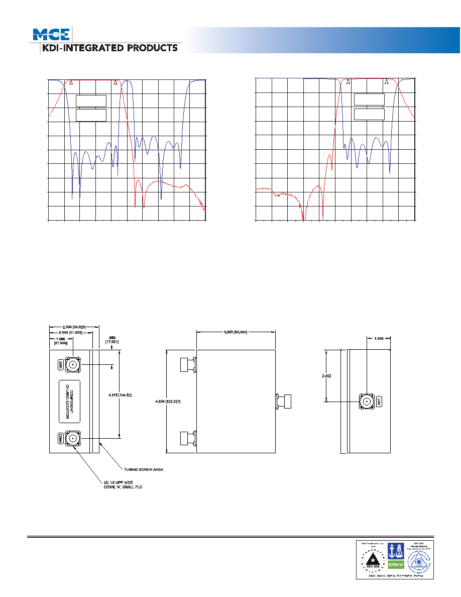
Physical Dimensions:
Model DCF-A02
NOTE: All dimensions are given in inches (mm) and are nominal, unless otherwise specified.
CONNECTORS:
GSM, CDMA, Antenna ports: Standard Type N Female connectors
-100
-90
-80
-70
-60
-50
-40
-30
-20
-10
0
795
815
835
855
875
895
915
935
955
975
995
Frequency (MHz)
dB
(S
(2
,
1
))
-50
-45
-40
-35
-30
-25
-20
-15
-10
-5
0
dB
(S
(1
,
1
))
M2
M1=909MHz
S21=-0.400dB
M1
M2=960MHz
S21=-0.580dB
CDMA Filter Rejection Response
GSM Filter Rejection Response
-100
-90
-80
-70
-60
-50
-40
-30
-20
-10
0
795
815
835
855
875
895
915
935
955
975
995
Frequency (MHz)
dB
(S
(2
,
1
))
-50
-45
-40
-35
-30
-25
-20
-15
-10
-5
0
dB
(S
(1
,
1
))
M2
M1=824MHz
S21=-0.375dB
M1
M2=880MHz
S21=-0.561dB