10/98
An MCE Company
TRIANGLE
C O R P O R A T I O N
KEY: Inches[Millimeters] .XX ±.03 .XXX ±.010 [.X ±0.8 .XX ±0.25]
60 South Jefferson Road, Whippany, NJ 07981
Tel: 973-887-8100 ∑ Fax: 973-884-0445
E-Mail: kdisales@aol.com
See us on the web @ www.kditriangle.com
DIODE
TRANSFER SWITCHES SERIES DTS
0.025 - 18 GHz
GENERAL INFORMATION
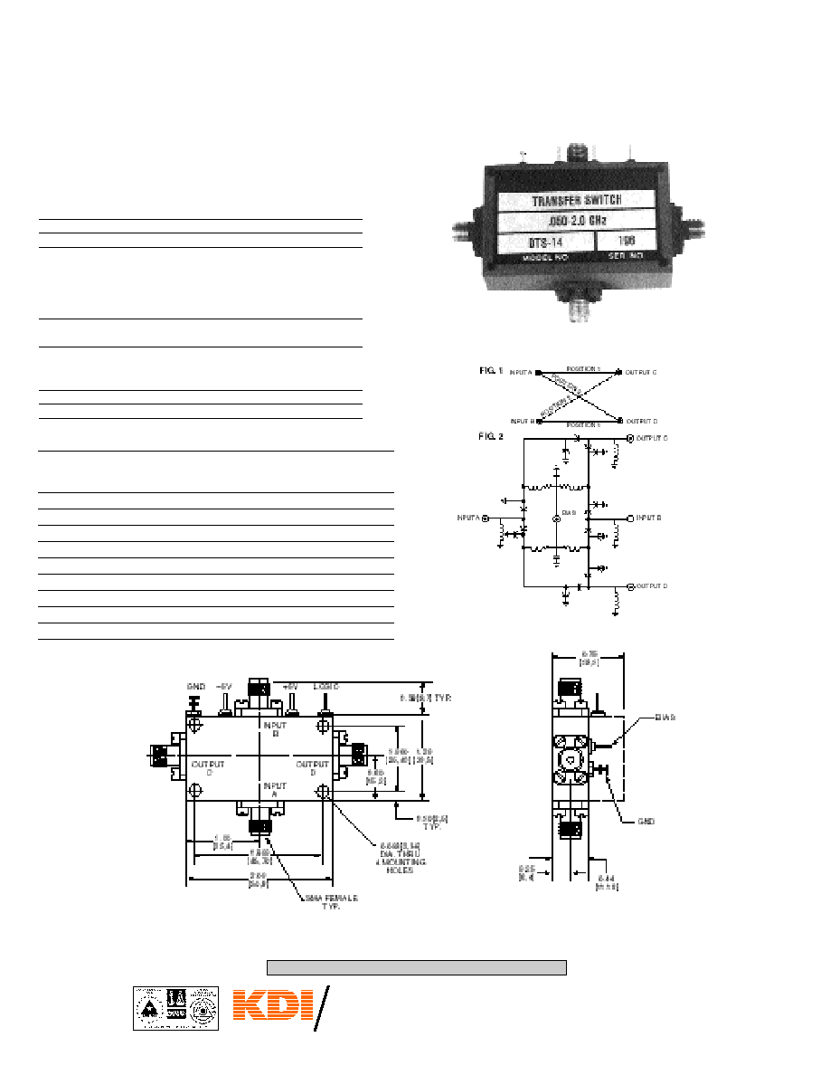
Series DTS transfer switches allow power entering two input ports, A
and B, to exit from output ports C and D respectively, or by appropriate
switching, to exit from ports D and C respectively. A functional schemat-
ic of a transfer is shown in Fig. 1, and a typical circuit is shown in Fig. 2.
GENERAL SPECIFICATIONS
Frequency Coverage: 0.025 to 18.0 GHz.
RF Impedance: 50 OHMS.
DC Requirements: For all units with driver
Logic "0" = Ins. Loss A
C, B
D
Isol. A
D, B
C
Logic "1" = Ins. Loss A
D, B
C
Isol. A
C, B
D
Temperature Information: Operating temperature from ≠55∞C to
+85∞C.
Switching Speed: 10% to 90% or 90% to 10% of RF. There
is an additional 20 nanosec of driver
delay.
Typical: 1 sec
Connectors: SMA
Frequency Ins Isolation Maximum Power
Model Range Loss dB VSWR dB Handling Ability
No. GHz Maximum Maximum Minimum Watts PK Watts Avg.
DTS-12 0.025-0.25 0.75 1.6 60 5 1.0
DTS-18 0.10-0.50 1.0 1.5 60 5 1.0
DTS-27 0.5-1.0 0.8 1.5 60 2 0.5
DTS-29 0.5-2.0 1.0 1.5 60 5 1.0
DTS-33 1.0-2.0 1.0 1.5 60 2 0.5
DTS-45 1.7-2.4 1.2 1.5 50 5 1.0
DTS-48 2.0-4.0 1.5 1.5 50 2 0.5
DTS-58 4.0-8.0 1.8 1.6 40 5 1.0
DTS-75 6.0-18.0 3.2 2.0 30 2 0.5
ELECTRICAL PERFORMANCE