
GENERAL INFORMATION
An analog phase shifter continuously changes the phase of a
microwave signal by varying a D.C. voltage. Since the D.C. voltage
applied to the diode is a reverse bias, the current drain is negligible
(typically less than 10 microamps). A balanced stripline configuration
keeps the VSWR and amplitude ripple to a minimum for all values of
phase.
GENERAL SPECIFICATIONS
Frequency Coverage: 0.1 to 18.0 GHz
RF impedance: 50 OHMS.
D.C. Voltage: 0 volts to +28 volts (standard), or 0 volts
to ≠28 volts (optional) will vary the phase
of any of the models over the minimum
phase shift listed
RF Power: 10 mW peak or CW, operating. Destruct
level is 1 W, CW, 100 W peak.
Temperature Information: The units can be used over a ≠55∞C to
+85∞C temperature range. However, the
phase will change either ±5∞ or ±5%,
whichever is greater. If temperature com-
pensation is required, this can be done on
request. With compensation, the variation
can be held to ±1∞ or ±1%, whichever is
greater, from ≠55∞C to +85∞C. The size
remains the same. If compensation is
desired, add a suffix T to the model num-
ber (e.g., PQ-17T).
Switching Speed: Series PQ phase shifters can be driven
from any phase value to any other value
in 10 nanoseconds. With linearizers, the
response time is 50 nanoseconds. With
temperature compensation the response
time is 100 nanoseconds.
Connectors: SMA
Notes:
1. LINEARIZATION: For phase shifters with linearizers add a suffix L
to the model number (e.g., PQ-23L). Linearity is ±2.0∞ for phase
shifters for 150∞ or less, and ±4∞ for phase shifters between 150∞
and 360∞. With linearization, DC voltages of ±15V at ±30mA are
required. The control voltage is 0≠10 volts. A control voltage of 0≠5
volts can be supplied at no additional cost, by adding a suffix 5 to
the model number (e.g. PQ-23L5). Linearity is measured at f
c
.
2. PHASE FLATNESS: The phase shift varies with frequency at any
voltage setting. This variation, referenced to 0∞ at 0 volts for each
frequency, is approximately ±15% for octave models, ± 10% for
models with 25% bandwidth, and ±7.5% for models with a 10%
bandwidth.
3. A connector, (SMA Female) is available in place of the bias pin at
no extra charge. This will be placed at the center of the surface
marked F on the drawing. This is the 0.38
◊
A surface. If a SMA
Female is desired, add suffix C to the model number (e.g., PQ-
23C).
4. Monotonicity guaranteed for all models.
0 5 10 15 20 25 30
150
120
90
60
30
P
H
A
S
E
S
H
I
F
T
(
D
E
G
R
E
E
S
)
PHASE
SHIFT
INSERTION
LOSS
.8
.6
.4
.2
0
1.0
I
N
S
E
R
T
I
O
N
L
O
S
S
(
d
B
)
VOLTAGE (V)
,,,,,,,,,,,,,,,,,,,
,,,,,,,,,,,,,,,,,,,
,,,,,,,,,,,,,,,,,,,
,,,,,,,,,,,,,,,,,,,
,,,,,,,,,,,,,,,,,,,
,,,,,,,,,,,,,,,,,,,
,,,,,,,,,,,,,,,,,,,
,,,,,,,,,,,,,,,,,,,
,,,,,,,,,,,,,,,,,,,
,,,,,,,,,,,,,,,,,,,
,,,,,,,,,,,,,,,,,,,
,,,,,,,,,,,,,,,,,,,
,,,,,,,,,,,,,,,,,,,
,,,,,,,,,,,,,,,,,,,
,,,,,,,,,,,,,,,,,,,
,,,,,,,,,,,,,,,,,,,
,,,,,,,,,,,,,,,,,,,
yyyyyyyyyyyyyyyyyyy
yyyyyyyyyyyyyyyyyyy
yyyyyyyyyyyyyyyyyyy
yyyyyyyyyyyyyyyyyyy
yyyyyyyyyyyyyyyyyyy
yyyyyyyyyyyyyyyyyyy
yyyyyyyyyyyyyyyyyyy
yyyyyyyyyyyyyyyyyyy
yyyyyyyyyyyyyyyyyyy
yyyyyyyyyyyyyyyyyyy
yyyyyyyyyyyyyyyyyyy
yyyyyyyyyyyyyyyyyyy
yyyyyyyyyyyyyyyyyyy
yyyyyyyyyyyyyyyyyyy
yyyyyyyyyyyyyyyyyyy
yyyyyyyyyyyyyyyyyyy
yyyyyyyyyyyyyyyyyyy
160
100
40
0.4 1.0 1.6
P
H
A
S
E
S
H
I
F
T
S
(
D
E
G
)
BIAS VOLTAGE VB (V)
Fig. 2
Phase shift characteristic of PQ-45.
Fig. 1
Typical Phase & Insertion Loss vs. Voltage Curves for PQ-31
ANALOG DIODE
PHASE SHIFTERS SERIES PQ
CONTINUOUSLY VARIABLE -- 0.1≠18 GHz
11-5-02
KEY: Inches[Millimeters] .XX ±.03 .XXX ±.010 [.X ±0.8 .XX ±0.25]
60 South Jefferson Road, Whippany, NJ 07981
Tel: 973-887-8100 ∑ Fax: 973-884-0445
email: sales@mcekdi-integrated.com
See us on the web @ www.mcekdi-integrated.com
An MCE Company
TRIANGLE
C O R P O R A T I O N
KEY: Inches[Millimeters] .XX ±.03 .XXX ±.010 [.X ±0.8 .XX ±0.25]
60 South Jefferson Road, Whippany, NJ 07981
Tel: 973-887-8100 ∑ Fax: 973-884-0445
E-Mail: kdisales@aol.com
See us on the web @ www.kditriangle.com
10/98
ELECTRICAL PERFORMANCE
Phase
Shift
Insertion
Amplitude
Note 2
Loss
Ripple
Outline
Frequency
Minimum Maximum Maximum
VSWR
No
With
Model No.* Range GHz
Degrees
dB
± dB
Maximum Linearizer Linearizer
PQ-12
0.1≠0.2
50
0.6
0.15
1.35
1
1
PQ-14
0.2≠0.4
50
0.6
0.15
1.35
1
1
PQ-17
0.25≠0.5
360
4.5
1.25
1.70
10
10
PQ-27
0.5≠1.0
180
3.0
0.4
1.50
3
3
PQ-28
0.5≠1.0
360
4.5
1.25
1.75
4
4
PQ-31
0.95≠1.25
120
1.2
0.15
1.40
1
1
PQ-33
1.0≠2.0
60
0.8
0.15
1.50
2
6
PQ-34
1.0≠2.0
360
4.5
1.5
1.80
8
4
PQ-39
1.7≠2.4
15
0.7
0.05
1.40
2
6
PQ-44
2.0≠4.0
180
3.0
0.50
1.60
3
3
PQ-45
2.0≠4.0
360
5.0
1.5
1.90
5
5
PQ-49
2.2≠2.3
180
2.0
0.30
1.50
3
3
PQ-59
4.0≠8.0
40
1.2
0.25
1.60
2
6
PQ-60
4.0≠8.0
360
8.0
1.5
1.90
9
9
PQ-65
6.0≠18.0
180
12.0
2.0
2.5
7
7
PQ-66
7.0≠12.4
360
12.0
2.0
2.20
9
9
PQ-72
8.0≠12.4
60
2.0
0.50
1.75
2
6
PQ-73
8.0≠10.0
180
5.0
1.0
1.75
7
7
PQ-74
8.0≠18.0
360
17.0
3.5
2.50
9
9
PQ-94
16.0≠17.0
50
2.0
0.20
1.65
2
6
0.40
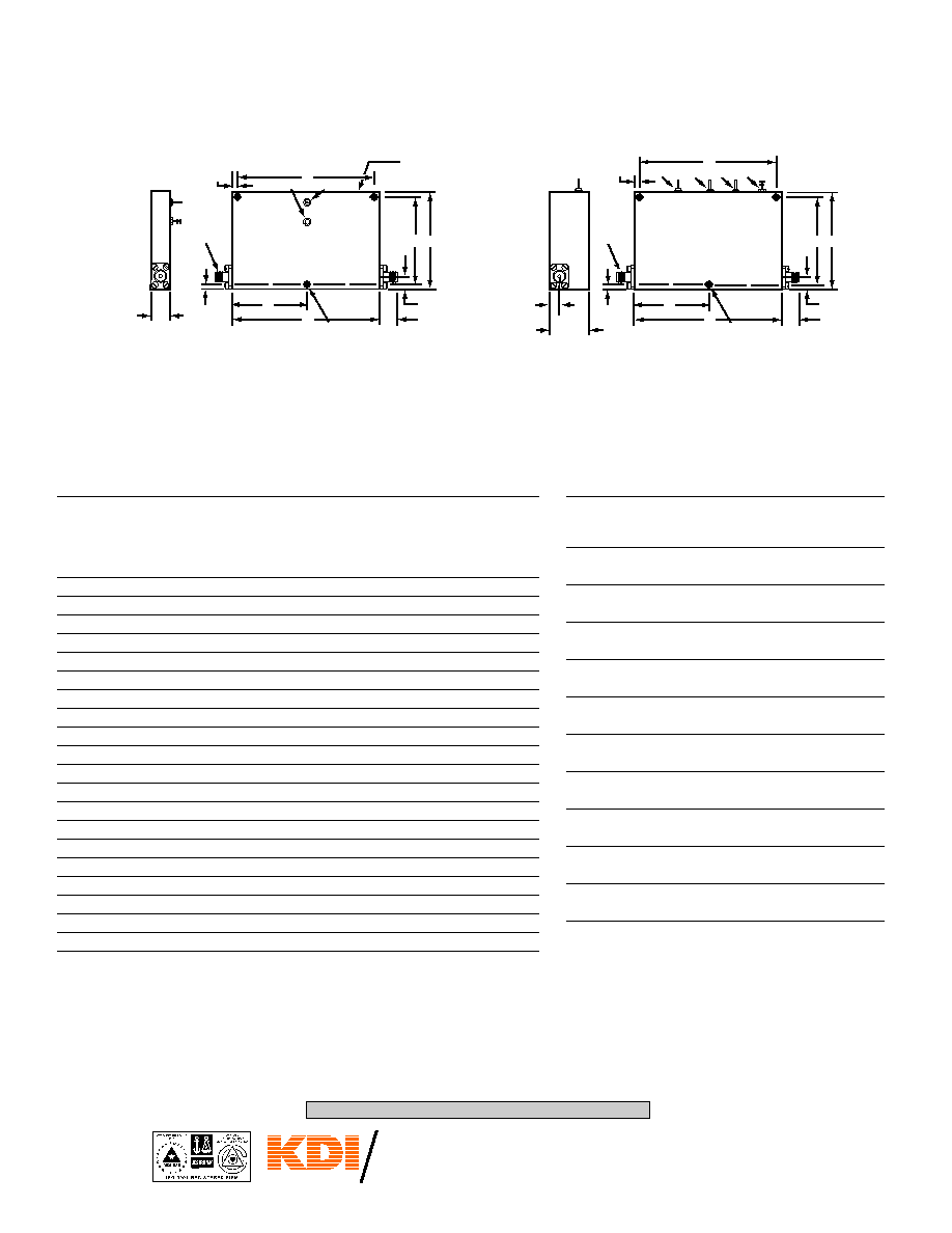
[10,2]
SMA
FEMALE
TYP.
RF
0.10[2,5]
TYP.
C
0.093[2,36]
DIA. THRU
3 MOUNTING
HOLES
A
F
0.38[9,7]
TYP.
RF
D
B
GROUND
BIAS PIN
F SURFACE
E
0.25[6,3]
1.00
[25,4]
SMA
FEMALE
TYP.
0.10[2,5]
TYP.
C
0.125[3,18]
DIA. THRU
3 MOUNTING
HOLES
A
F
0.38[9,7]
TYP.
D
B
GND
E
0.25[6,3]
0.20
[5,1]
RF
C.V.
+15V
≠15V
OUTLINE WITHOUT LINEARIZER OUTLINE WITH LINEARIZER
MECHANICAL OUTLINES
A
B
C
D
E
F
Out-
in
in
in
in
in
in
line
[mm]
[mm]
[mm]
[mm]
[mm]
[mm]
2.75
2.25
1.38
2.050
2.250
0.53
[69,91] [57,15] [35,05] [52,07]
[57,15] [13,46]
1.25
2.00
0.63
1.800
0.750
0.25
[31,75] [50,8]
[16,0]
[45,7]
[19,1]
[6,4]
5.00
2.00
N/A
1.800
4.500
0.25
[127,0]
[50,8]
4 holes
[45,7]
[114,3]
[6,4]
7.75
2.50
N/A
2.300
7.250
0.25
[196,8]
[63,5]
4 holes [58,42] [184,15]
[6,4]
6.50
2.00
N/A
1.800
6.000
0.25
[165,1]
[50,8]
4 holes
[45,7]
[152,4]
[6,4]
2.00
2.00
1.00
1.800
1.500
0.25
[50,8]
[50,8]
[25,4]
[45,7]
[38,1]
[6,4]
3.00
2.00
1.50
1.800
2.500
0.25
[76,2]
[50,8]
[38,1]
[45,7]
[63,5]
[6,4]
6.50
2.50
N/A
2.300
6.000
0.25
[165,1]
[63,5]
4 holes [58,42] [152,4]
[6,4]
5.00
2.00
N/A
1.800
4.500
0.50
[127,0]
[50,8]
4 holes
[45,7]
[114,3]
[12,7]
7.75
2.50
N/A
2.300
7.250
0.75
[196,8]
[63,5]
4 holes [58,42] [184,15] [19,1]
*OPTIONS: (Add to Model No.)
T
Temp. Comp.
L
Linearization
C
Bias Connector -- SMA
5
0 to 5 Volts Control Voltage for Linearized Models.
1
2
3
4
5
6
7
8
9
10
ANALOG DIODE
PHASE SHIFTERS SERIES PQ
CONTINUOUSLY VARIABLE -- 0.1≠18 GHz