
1
P/N:PM1084
REV. 0.0, MAR. 17, 2004
MX28F640C3BT/B
64M-BIT [4M x16] CMOS SINGLE VOLTAGE
3V ONLY FLASH MEMORY
ADVANCED INFORMATION
∑ Automatic Suspend Enhance
- Word write suspend to read
- Sector erase suspend to word write
- Sector erase suspend to read register report
∑ Automatic sector erase, full chip erase, word write and
sector lock/unlock configuration
∑ Status Reply
- Detection of program and erase operation comple-
tion.
- Command User Interface (CUI)
- Status Register (SR)
∑ Data Protection Performance
- Include boot sectors and parameter and main sectors
to be block/unblock
∑ 100,000 minimum erase/program cycles
∑ Common Flash Interface (CFI)
∑ 128-bit Protection Register
- 64-bit Unique Device Identifier
- 64-bit User-Programmable
∑ Latch-up protected to 100mA from -1V to VCC+1V
∑ Package type:
- 48-pin TSOP (12mm x 20mm)
FEATURES
∑ Bit Organization: 4,194,304 x 16
∑ Single power supply operation
- 3.0V only operation for read, erase and program
operation
- VCC=VCCQ=2.7~3.6V
- Operating temperature:-40
∞
C~85
∞
C
∑ Fast access time : 90/120ns
∑ Low power consumption
- 9mA maximum active read current, f=5MHz (CMOS
input)
- 21mA program erase current maximum
(VPP=1.65~3.6V)
- 7uA typical standby current under power saving
mode
∑ Sector architecture
- Sector Erase (Sector structure : 4Kword x 2 (boot
sectors), 4Kword x 6 (parameter sectors), 32Kword x
127 (parameter sectors)
- Top/Bottom Boot
∑ Auto Erase (chip & sector) and Auto Program
- Automatically program and verify data at specified
address
GENERAL DESCRIPTION
The MX28F640C3BT/B is a 64-mega bit Flash memory
organized as 4M words of 16 bits. The 1M word of data
is arranged in eight 4Kword boot and parameter sectors,
and 127 32Kword main sector which are individually
erasable. MXIC's Flash memories offer the most cost-
effective and reliable read/write non-volatile random ac-
cess memory. The MX28F640C3BT/B is packaged in
48-pin TSOP. It is designed to be reprogrammed and
erased in system or in standard EPROM programmers.
The standard MX28F640C3BT/B offers access time as
fast as 90ns, allowing operation of high-speed micropro-
cessors without wait states.
MXIC's Flash memories augment EPROM functionality
with in-circuit electrical erasure and programming. The
MX28F640C3BT/B uses a command register to man-
age this functionality. The command register allows for
100% TTL level control inputs and fixed power supply
levels during erase and programming, while maintaining
maximum EPROM compatibility.
MXIC Flash technology reliably stores memory contents
even after 100,000 erase and program cycles. The MXIC
cell is designed to optimize the erase and programming
mechanisms. In addition, the combination of advanced

2
P/N:PM1084
MX28F640C3BT/B
REV. 0.0, MAR. 17, 2004
tunnel oxide processing and low internal electric fields
for erase and program operations produces reliable cy-
cling. The MX28F640C3BT/B uses a 2.7V~3.6V VCC
supply to perform the High Reliability Erase and auto
Program/Erase algorithms.
The highest degree of latch-up protection is achieved
with MXIC's proprietary non-epi process. Latch-up pro-
tection is proved for stresses up to 100 milliamps on
address and data pin from -1V to VCC + 1V.
The dedicated VPP pin gives complete data protection
when VPP< VPPLK.
A Command User Interface (CUI) serves as the inter-
face between the system processor and internal opera-
tion of the device. A valid command sequence written to
the CUI initiates device automation. An internal Write
State Machine (WSM) automatically executes the algo-
rithms and timings necessary for erase, full chip erase,
word write and sector lock/unlock configuration opera-
tions.
A sector erase operation erases one of the device's 32K-
word sectors typically within 1.0s, 4K-word sectors typi-
cally within 0.5s independent of other sectors. Each sec-
tor can be independently erased minimum 100,000 times.
Sector erase suspend mode allows system software to
suspend sector erase to read or write data from any other
sector.
Writing memory data is performed in word increments of
the device's 32K-word sectors typically within 0.8s and
4K-word sectors typically within 0.1s. Word program sus-
pend mode enables the system to read data or execute
code from any other memory array location.
MX28F640C3BT/B features with individual sectors lock-
ing by using a combination of bits thirty-nine sector lock-
bits and WP#, to lock and unlock sectors.
The status register indicates when the WSM's sector
erase, full chip erase, word program or lock configura-
tion operation is done.
The access time is 90/120ns (tELQV) over the operat-
ing temperature range (-40
∞
C to +80
∞
C) and VCC supply
voltage range of 2.7V~3.6V.
MX28F640C3BT/B's power saving mode feature sub-
stantially reduces active current when the device is in
static mode (addresses not switching). In this mode, the
typical ICCS current is 7uA (CMOS) at 3.0V VCC.
As CE# and RESET# are at VCC, ICC CMOS standby
mode is enabled. When RESET# is at GND, the reset
mode is enabled which minimize power consumption and
provide data write protection.
A reset time (tPHQV) is required from RESET# switch-
ing high until outputs are valid. Similarly, the device has
a wake time (tPHEL) from RESET#-high until writes to
the CUI are recognized. With RESET# at GND, the WSM
is reset and the status register is cleared.
3
P/N:PM1084
MX28F640C3BT/B
REV. 0.0, MAR. 17, 2004
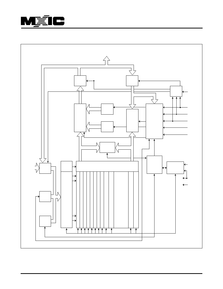
BLOCK DIAGRAM
Output
Buffer
Output
Multiple
x
e
r
Data
Register
Q0~Q7
Identifier
Register
Command
User
Interface
Input
Buffer
Status
Register
Data
Comparator
Y-Gating
32K-Word
Main Sector
x127
.......
.......
Boot Sector 0
Boot Sector 1
P
a
r
ameter Sector 0
P
a
r
ameter Sector 1
P
a
r
ameter Sector 2
P
a
r
ameter Sector 3
P
a
r
ameter Sector 4
P
a
r
ameter Sector 5
Main Sector 0
Main Sector 1
Main Sector 125
Main Sector 126
Write
State
Machine
Program/Erase
Voltage Switch
Y
Decoder
Input
Buffer
A0~A21
Address
Latch
Address
Counter
X
Decoder
I/O
Logic
VCC
CE#
WE#
OE#
RESET#
WP#
VPP
VCC
GND

4
P/N:PM1084
MX28F640C3BT/B
REV. 0.0, MAR. 17, 2004
PIN CONFIGURATIONS
48 TSOP (Standard Type) (12mm x 20mm)
A15
A14
A13
A12
A11
A10
A9
A8
A21
A20
WE#
RESET#
VPP
WP#
A19
A18
A17
A7
A6
A5
A4
A3
A2
A1
1
2
3
4
5
6
7
8
9
10
11
12
13
14
15
16
17
18
19
20
21
22
23
24
A16
VCCQ
GND
Q15
Q7
Q14
Q6
Q13
Q5
Q12
Q4
VCC
Q11
Q3
Q10
Q2
Q9
Q1
Q8
Q0
OE#
GND
CE#
A0
48
47
46
45
44
43
42
41
40
39
38
37
36
35
34
33
32
31
30
29
28
27
26
25
MX28F640C3T/B
Table 1. Pin Description
Symbol
Type
Description and Function
A0-A21
input
Address inputs for memory address. Data pin float to high-impedance when the chip is
deselected or outputs are disable. Addresses are internally latched during a write or erase
cycle.
Q0-Q15 input/output
Data inputs/outputs: Inputs array data on the second CE# and WE# cycle during a program
command. Data is internally latched. Outputs array and configuration data. The data pin float
to tri-state when the chip is de-selected.
CE#
input
Activates the device's control logic, input buffers, and sense amplifiers. CE# high de-se-
lects the memory device and reduce power consumption to standby level. CE# is active low.
RESET#
input
Reset Deep Power Down: when RESET#=VIL, the device is in reset/deep power down
mode, which drives the outputs to High Z, resets the WSM and minimizes current level.
When RESET#=VIH, the device is normal operation. When RESET# transition the device
defaults to the read array mode.
WE#
input
Write Enable: to control write to CUI and array sector. WR#=VIL becomes active. The data
and address is latched WE# on the rising edge of the second WE# pulse.
VPP
input/supply
Program/Erase Power Supply:(1.65V~3.6V or 11.4V~12.6V)
Lower VPP<VPPLK, to protect any contents against Program and Erase Command.
Set VPP=VCC for in-system Read, Program and Erase Operation.
Raise VPP to 12V
±
5% for faster program and erase in a production environment.
OE#
input
Output enable: gates the device's outputs during a real cycle.
WP#
input
Write protect: when WP# is VIL, the boot sectors cannot be written or erased. When WP# is
VIH, locked boot sectors cannot be written or erase. WP is not affected parameter and main
sectors.
VCC
supply
Device power supply: (2.7V~3.6V).
VCCQ
input
I/O Power Supply: supplies for input/output buffers.
[2.7V~3.6V] This input should be tied directly to VCC.
GND
supply
Ground voltage: all the GND pin shall not be connected.
5
P/N:PM1084
MX28F640C3BT/B
REV. 0.0, MAR. 17, 2004
SECTOR STRUCTURE (TOP)
Sector
Sector Size
Address Range (h)
Boot Sector 0
4K Word
3FF000-3FFFFF
Boot Sector 1
4K Word
3FE000-3FEFFF
Parameter Sector 0
4K Word
3FD000-3FDFFF
Parameter Sector 1
4K Word
3FC000-3FCFFF
Parameter Sector 2
4K Word
3FB000-3FBFFF
Parameter Sector 3
4K Word
3FA000-3FAFFF
Parameter Sector 4
4K Word
3F9000-3F9FFF
Parameter Sector 5
4K Word
3F8000-3F8FFF
Main Sector 0
32K Word
3F0000-3F7FFF
Main Sector 1
32K Word
3E8000-3EFFFF
Main Sector 2
32K Word
3E0000-3E7FFF
Main Sector 3
32K Word
3D8000-3DFFFF
Main Sector 4
32K Word
3D0000-3D7FFF
Main Sector 5
32K Word
3C8000-3CFFFF
Main Sector 6
32K Word
3C0000-3C7FFF
Main Sector 7
32K Word
3B8000-3BFFFF
Main Sector 8
32K Word
3B0000-3B7FFF
Main Sector 9
32K Word
3A8000-3AFFFF
Main Sector 10
32K Word
3A0000-3A7FFF
Main Sector 11
32K Word
398000-39FFFF
Main Sector 12
32K Word
390000-397FFF
Main Sector 13
32K Word
388000-38FFFF
Main Sector 14
32K Word
380000-387FFF
Main Sector 15
32K Word
378000-37FFFF
Main Sector 16
32K Word
370000-377FFF
Main Sector 17
32K Word
368000-36FFFF
Main Sector 18
32K Word
360000-367FFF
Main Sector 19
32K Word
358000-35FFFF
Main Sector 20
32K Word
350000-357FFF
Main Sector 21
32K Word
348000-34FFFF
Main Sector 22
32K Word
340000-347FFF
Main Sector 23
32K Word
338000-33FFFF
Main Sector 24
32K Word
330000-337FFF
Main Sector 25
32K Word
328000-32FFFF
Main Sector 26
32K Word
320000-327FFF
Main Sector 27
32K Word
318000-31FFFF
Main Sector 28
32K Word
310000-317FFF
Main Sector 29
32K Word
308000-30FFFF
Main Sector 30
32K Word
300000-307FFF
Sector
Sector Size
Address Range (h)
Main Sector 31
32K Word
2F8000-2FFFFF
Main Sector 32
32K Word
2F0000-2F7FFF
Main Sector 33
32K Word
2E8000-2EFFFF
Main Sector 34
32K Word
2E0000-2E7FFF
Main Sector 35
32K Word
2D8000-2DFFFF
Main Sector 36
32K Word
2D0000-2D7FFF
Main Sector 37
32K Word
2C8000-2CFFFF
Main Sector 38
32K Word
2C0000-2C7FFF
Main Sector 39
32K Word
2B8000-2BFFFF
Main Sector 40
32K Word
2B0000-2B7FFF
Main Sector 41
32K Word
2A8000-2AFFFF
Main Sector 42
32K Word
2A0000-2A7FFF
Main Sector 43
32K Word
298000-29FFFF
Main Sector 44
32K Word
290000-297FFF
Main Sector 45
32K Word
288000-28FFFF
Main Sector 46
32K Word
280000-287FFF
Main Sector 47
32K Word
278000-27FFFF
Main Sector 48
32K Word
270000-277FFF
Main Sector 49
32K Word
268000-26FFFF
Main Sector 50
32K Word
260000-267FFF
Main Sector 51
32K Word
258000-25FFFF
Main Sector 52
32K Word
250000-257FFF
Main Sector 53
32K Word
248000-24FFFF
Main Sector 54
32K Word
240000-247FFF
Main Sector 55
32K Word
238000-23FFFF
Main Sector 56
32K Word
230000-237FFF
Main Sector 57
32K Word
228000-22FFFF
Main Sector 58
32K Word
220000-227FFF
Main Sector 59
32K Word
218000-21FFFF
Main Sector 60
32K Word
210000-217FFF
Main Sector 61
32K Word
208000-20FFFF
Main Sector 62
32K Word
200000-207FFF
Main Sector 63
32K Word
1F8000-1FFFFF
Main Sector 64
32K Word
1F0000-1F7FFF
Main Sector 65
32K Word
1E8000-1EFFFF
Main Sector 66
32K Word
1E0000-1E7FFF
Main Sector 67
32K Word
1D8000-1DFFFF
Main Sector 68
32K Word
1D0000-1D7FFF
Main Sector 69
32K Word
1C8000-1CFFFF
Main Sector 70
32K Word
1C0000-1C7FFF