 | –≠–ª–µ–∫—Ç—Ä–æ–Ω–Ω—ã–π –∫–æ–º–ø–æ–Ω–µ–Ω—Ç: MLX90108 | –°–∫–∞—á–∞—Ç—å:  PDF PDF  ZIP ZIP |
MLX90108
64bit Read Only Transponder
3901090108
Page 1 of 9
Sep/02
Rev. 002
Features
∑
125kHz range
∑
Very small chip size
∑
Optimized for Low cost
∑
Integrated tuning and buffer capacitance
∑
Low power consumption, for maximum operating distance
∑
Deep modulation for maximum reading distance
∑
Mask programmable modulation schemes and data rates.
∑
Available with MEGAPADS.
Applications
∑
Automotive Key, Access control, ID cards, Laundry ticketing, Consumer goods, Industrial and
Medical Applications
Ordering Information
Part No.
Temperature Suffix
Package
Mask version (Encoding @Baudrate)
MLX90108
C (0∞C to 70∞C)
UH
-A
(Manchester @4kBaud)
MLX90108
C (0∞C to 70∞C)
UH
-B
(Manchester @2kBaud)
MLX90108
C (0∞C to 70∞C)
UH
-C
(Biphase @4kBaud)
MLX90108
C (0∞C to 70∞C)
UH
-D
(Biphase @2kBaud)
MLX90108
C (0∞C to 70∞C)
UH
-G
(PSK @8kBaud)
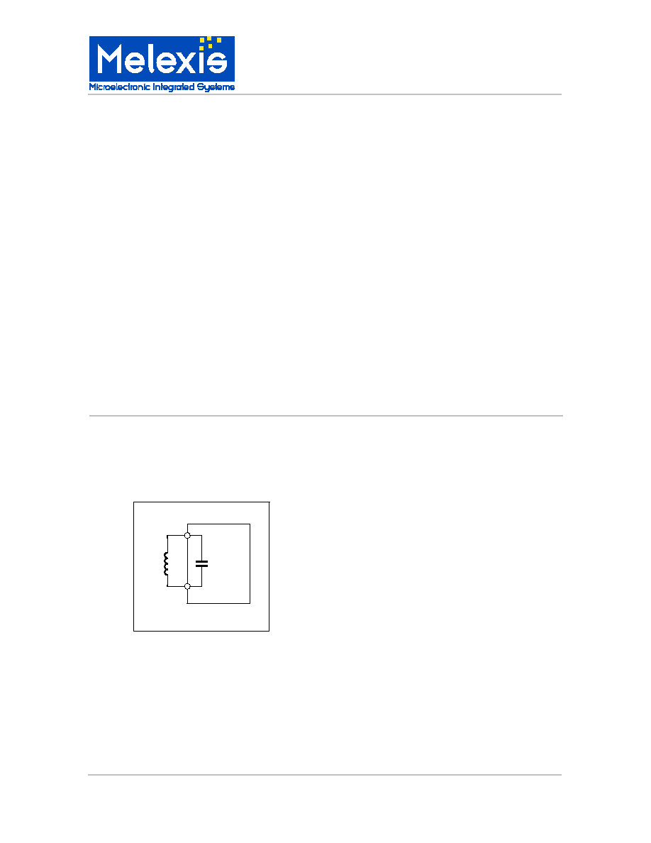
1. Functional Diagram
2. Description
The MLX90108 is a dedicated 64 bit Read Only
(RO) Transponder (TAG) for the 125kHz range.
Clock and power supply are taken from the
electromagnetic field. By switching a resistor in
parallel to the resonant circuit formed by the
integrated tuning capacitor and the external coil,
the
transponder
amplitude
modulates
the
electromagnetic field. Encoding of the data and
data rate depend on the version.
It is a low cost solution for high volume
applications. The tuning and buffer capacitors are
integrated on chip.
The unique identification code (ID) is EEPROM
programmed in test mode during probing. Data
coding and data rate are mask programmed. An
optimized layout for gold bumps (MEGAPADS)
and a standard version are available for all
options. This allows the device to be integrated
into any assembly form.
90108
DUT

MLX90108
64bit Read Only Transponder
3901090108
Page 2 of 9
Sep/02
Rev. 002
CONTENTS
ORDERING INFORMATION.................................................................................................................... 1
1.
FUNCTIONAL DIAGRAM................................................................................................................. 1
2.
DESCRIPTION ................................................................................................................................. 1
3.
MLX90108 ELECTRICAL SPECIFICATIONS ................................................................................... 3
4.
GENERAL DESCRIPTION ............................................................................................................... 4
4.1.
FREQUENCY TUNING..................................................................................................................... 4
4.2.
CLOCK EXTRACTOR: ..................................................................................................................... 4
4.3.
VDD REGULATOR: ......................................................................................................................... 4
4.4.
POR LEVEL ..................................................................................................................................... 4
4.5.
SENSITIVITY LEVEL........................................................................................................................ 4
4.6.
MODULATOR .................................................................................................................................. 4
4.7.
EEPROM.......................................................................................................................................... 4
5.
CODING SCHEMES......................................................................................................................... 5
5.1.
BIPHASE/MANCHESTER AM.......................................................................................................... 5
5.2.
PHASE SHIFT KEYING (PSK) AM................................................................................................... 5
6.
UNIQUE FEATURES........................................................................................................................ 6
7.
CROSS REFERENCE ...................................................................................................................... 6
8.
ABSOLUTE MAXIMUM RATINGS ................................................................................................... 6
9.
ESD PRECAUTIONS........................................................................................................................ 6
10.
GENERAL REMARKS. .................................................................................................................... 6
11.
DATA CODING STRUCTURE. ........................................................................................................ 6
12.
PACKAGE INFORMATION .............................................................................................................. 6
12.1.
PACKAGE CODES: .................................................................................................................. 6
12.2.
CHIP DIMENSIONS................................................................................................................... 6
12.3.
BLISTER TAPE ......................................................................................................................... 7
13.
DISCLAIMER ................................................................................................................................... 8

MLX90108
64bit Read Only Transponder
3901090108
Page 3 of 9
Sep/02
Rev. 002
3. MLX90108 Electrical Specifications
All specifications are valid for Manchester, Biphase and PSK encoding, and for 2kbaud and 4kbaud and
8kbaud data rate options,
Toper = -40
∞
C to 85
∞
C,
Operating frequency = 120kHz
(unless otherwise specified)
Parameter
Symbol Test Conditions
Min
Typ
Max
Units
Sensitivity level Manch/Biph
Vac
(2)
150
180 mVpp
Sensitivity level PSK
Vac
(2)
400
600 mVpp
EEPROM data retention
Tret
Critical reading ID, Toper=25
o
C
10
100
year
Modulation Depth ASK
VweakL
Weak power: Vac = 200mVpp, Mod ON
0.3
0.8 Vpp
VweakH
Weak power: Vac = 200mVpp, Mod OFF
3
5
Vpp
VmedL
Medium power: Vac = 4.8Vpp, Mod ON
5
7
Vpp
VmedH
Medium power: Vac = 4.8Vpp, Mod OFF
14
18
Vpp
Coil-GND tune capacitor
Toper=25
o
C, Vdut=1Vpp
77.2
80
82.8 pF(4)
Operational Coil-GND tune
capacitor
Ctune
Toper=25
o
C, Vdut = 6Vpp
85
pF
IclampLow
VdutDC = +/- 2V
40
700 nA
DC input current clamping
IclampHigh
VdutDC = +/- 10V
3.5
10 mA
Notes:
Note (1): All specification values are tested 100%, or guaranteed by design.
Note (2): Continuous (without POR restart) normal reading of the 64bit ID on test set up as depicted.
Note (3): Statistical spread on wafer basis within one lot is 3.5%.
Temperature shift is typically -0.5% on -40
∞
C, and +1% at 85
∞
C.
On the MLX90108 a maximum Lot to lot spread of 20% is possible: average of a lot can vary
between 64 and 96pF.
Vac
5
0
90108
DUT
Vdut
C1
C2
Cpar=10pF
L=6.8mH
Qrc @ 120KHz=48.8
C1+C2=250pF
Vin
COIL
GND

MLX90108
64bit Read Only Transponder
3901090108
Page 4 of 9
Sep/02
Rev. 002
Coil
GND
Clock
extractor
Divider by
64, 32 or 16
Modulator
Memory
Array
C
TUNE
C
BUFFER
Data encoder
Sequencer
VDD
regulator
AC
+
VDD
VDD
MLX90108
4. General Description
The MLX90108 is a 64 bit Read Only (RO)
transponder. The integrated tune capacitance and the
external coil form a resonant LC antenna that absorbs
part of the electromagnetic energy radiated by the
transceiver LC antenna. Physically, a magnetic
coupling occurs between the transceiver, also referred
to as "reader", and transponder antennas
To amplitude modulate (AM) the RF carrier, the
transponder damps the electromagnetic field by
switching a resistor in parallel with its coil. This way
the transponder repetitively transmits its 64 bit-
identification code (ID) to the reader base station.
4.1. Frequency tuning
Tuning and buffer capacitors are integrated to optimize
total system cost.
The 80pF integrated tuning capacitor is +/-20%
accurate from batch to batch. A spread of max +/-
2.5% is guaranteed across a full batch, which is
typically 200k dice.
4.2. Clock Extractor:
Master clock is taken from the carrier frequency which
is picked up on the coil. Depending on the options, the
carrier frequency is divided by 16(8kBaud: PSK only),
32(4kbaud) or 64(2kbaud)to generate the bit rate.
4.3. VDD regulator:
Supply voltage is taken from the AC voltage induced in
the coil. Overvoltage protection is done by current
clamping.
4.4. POR level
When the transponder is placed in an external radio
frequency (RF) field of appropriate frequency and
amplitude, the internal power supply (VDD) can build
up as charge on the integrated buffer capacitance.
The modulation resistor is switched on and off as soon
as VDD has reached the Power On Reset (POR) level.
When the modulation resistor is switched on, the LC
circuit is no longer tuned, therefore no energy is taken
from the field, and VDD drops due to internal
consumption. Hence, by switching the modulation
resistor on and off, it is possible to oscillate around the
POR level. This phenomenon is referred to as
hiccuping.
The modulation resistor is switched off when the
transponder drops below the POR level.
4.5. Sensitivity level
The minimum electromagnetic force (e.m.f.) needed to
avoid hiccuping is defined by Vacsens. At this level
the power supply will not drop below the POR level
while the modulation resistance is switched on during
modulation.
4.6. Modulator
The modulator consists of a modulation resistor that is
switched in parallel with the resonant LC circuit
(antenna). The MLX90108 offers different encoding
schemes and AM modulation techniques, which are
discussed below, each optimized for maximum
operating and reading distance under different field
conditions.
4.7. EEPROM
The Identification code is written in EEPROM during
wafer test. After POR the device will read out the data
periodically. Data retention is guaranteed as specified
(Tret, Ncyc).
Block diagram
MLX90108
64bit Read Only Transponder
3901090108
Page 5 of 9
Sep/02
Rev. 002
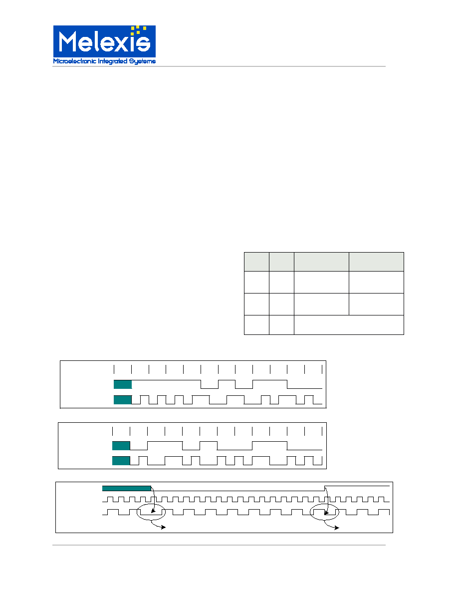
X
1
1
1
1
0
1
0
Binary Data
Modulation Output
1
1
0
0
Memory Output
Manchester Code
5. Coding schemes
5.1. Biphase/Manchester AM
Biphase and Manchester are Amplitude Modulation
encoding schemes, which rely on the build up of the
voltage on the transponder resonant circuit during a
certain period, defined by the baudrate.
In weak RF fields the quality factor of the transponder
antenna is significant, therefore the rising edge is
much slower than the falling edge of the envelope.
Consequently a symmetrically driven modulator gives
an asymmetrical envelope on the reader antenna.
This is anticipated by delaying each falling edge by a
fixed number of RF clock pulses. The modulator is
hence driven asymmetrical. Each ON state is reduced
by 8 (4) clocks in 2 (4) kBaud mode, and each OFF
state is prolonged by the same amount. This
guarantees good reading in strong and weak fields, at
large distance and in proximity of the reader antenna.
Manchester:
For a "1" bit, there is a transition from 0 to 1 in the
middle of the bit period. Reciprocal, for a "0" logic bit
there is a transition from 1 to 0 in the middle of the bit
period.
Biphase:
At the beginning of each bit, a transition will occur. A
logic bit "1" will keep its state for the whole bit duration
and a logic bit "0" will show a transition in the middle of
the bit duration.
5.2. Phase Shift keying (PSK) AM
PSK is an Amplitude Modulation encoding scheme
that relies on the change of phase of the modulation.
Every other period, i.e. at half the carrier frequency,
the field is modulated. Therefore the voltage can not
build up on the transponder resonant circuit, and
hence the sensitivity level is much higher than for the
other coding schemes.
Each data bit lasts for 16 carrier periods. A 180∞ phase
shift occurs at the beginning of a data bit when a logic
"0" is read from the memory. There is no phase shift
when a logic "1" is read from the memory.
PSK readers operate in the frequency domain.
Therefore the demodulation is insensitive to skew in
the time domain.
The modulation depth is still optimized for different
field strengths, and reading distances.
Speed Clocks
per Bit
Clocks `ON' state Clocks `OFF' state
2kbaud
(MAN/BI)
64
Long ON = 64 - 8
Short ON = 32 - 8
Long ON = 64 + 8
Short ON = 32 + 8
4kbaud
(MAN/BI)
32
Long ON = 32 ≠ 4
Short ON = 16 ≠ 4
Long ON = 32 + 4
Short ON = 16 + 4
8kBaud
(PSK)
16
No asymmetrical behavior
PSK Code
Memory output
coil
Modulation output
"0" on serial out
"1" on serial out
X
0
1
1
0
1
0
0
Binary Data
Modulation Output
1
1
0
0
Memory Output
Biphase Coding