
MLX902xx Name of Sensor
Rev Y.X
22/Aug/98
Page 1
CMOS Power Hall IC
3901000079
Page 1
Aug/02
Rev. 005
Features and Benefits
Built-in Reverse Voltage Protection
Built-in RFI Filter
Power Efficient CMOS and Power MOSFET Drivers allow 400mA without overheating
Built-in Zener Diodes Protect Outputs
Eliminates all Fan Components
Eliminate PC Board
5V and 12V Operation
High Sensitivity for switching symmetry
Locked Rotor Shutdown
Applications
Fan Sizes up to 90mm
Current Range up to 400mA
Ordering Information
Part No.
Temperature Suffix
Package
US79
K ( -40
o
C to 125
o
C )
UA (TO-92 flat)
Description
The US79KUA is the most advanced Smart Fan
Control Hall IC. It is designed for 5V and 12V cooling
commutation. The chip contains many features to
allow survival in a harsh environment. The IC was
designed to eliminate all discrete components such
as capacitors, resistors, transistors, diodes, PC
board and associated labor, replacing US$0.25 to
US$0.35 in direct cost.
The K rating guarantees proper operation up to an
ambient temperature of 125�C. Hall IC circuitry and
power FET output provide a low power dissipation
cool chip.
Locked Rotor conditions are detected by the IC when
there is no motion for one second and will shut off
the motor drive for five seconds. Then, the IC will
turn on the drive current for one second. This
sequence continues indefinitely until the locked rotor
condition is fixed. This feature prevents overheating.
Functional Diagram
Voltage
Regulator
1
2
3
Hall Latch
Output 1
Output 2
Control and
Protection
GND
-
+
CMOS Power Hall IC
3901000079
Page 2
Aug/02
Rev. 005
US79 Electrical Specifications
DC operating parameters: T
A
= 25
o
C, V
DD
= 5.0 to 12V unless otherwise specified.
Parameter
Test Conditions
Min Typ Max Units
Supply Voltage
V
DD
Operating
3.5
-
18
V
Supply Current
I
DD
Operating
2.0
4
mA
Output voltage
V
OUT
B<B
HYS
-
-
34
V
Output Saturation voltage
V
DSS
I
OUT
= 150mA
300 600
mV
Output Saturation voltage
V
DSS
I
OUT
= 350mA
650 1100
mV
Output On resistance
R
DDSS
1.84
Thermal resistance
R
th
Operating
190
�C/Watt
US79 Magnetic Specifications
DC operating parameters: T
A
= 25
o
C, V
DD
= 5.0 to 12V unless otherwise specified. 1 mT = 10 Gauss.
Parameter
Symbol Test Conditions
Min Typ Max Units
Operate Point
B
OP
Operating
2.5
6.0
mT
Release Point
B
RP
Operating
-6.0
-2.5
mT
Hysteresis
B
HYS
Operating
-
5.0
-
mT
General Description
The US79 eliminates 16 solder joints, protects
against ESD, filters RFI emission caused by
switching of high currents, protects against voltage
surges, protects against locked rotor, operates at a
low temperature and is manufactured in an
Automotive IC factory.
Unique Features
Reverse voltage protection eliminates the need for a
diode. Reverse current flows through the coils and
the chip. Power dissipation is (2 * Istall/start * 0.7V).
Table 1 presents max temperature for each current.
I
stall
/ I
start
T
A
Maximum Rev V Test
100mA
125�C
200mA
100�C
300mA
70�C
400mA
40�C
Reverse Voltage protection is provided by the motor
windings. The IC contains slew rate control on the
output drivers to eliminate RF emissions. 35V Zener
diodes clamp the output drivers for overstress
protection.
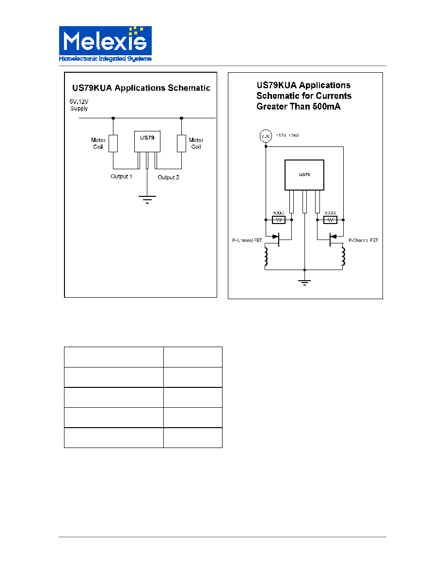
Application Comments
EMC protection is built in. EMC considerations
require that the fan assembly should tolerate ESD,
reverse voltage, over voltage and not radiate RF
noise which may interfere with other electronic
equipment. These capabilities are built in to the chip
to meet EMC requirements.
Qualification Test Results
SOA (Safe Operating Area) tests to verify inductive
switching of 500mA @ 20V. 1000 pieces tested 100
cycles each. Operating Life Test at TA = 150C for
4000 hrs. 100pc. "0" failures. Package qualified to
QS900 automotive specifications.
MLX902xx Name of Sensor
Rev Y.X
22/Aug/98
Page 3
CMOS Power Hall IC
3901000079
Page 3
Aug/02
Rev. 005
Absolute Maximum Ratings
Supply Voltage (Over Voltage), V
DD
18V
Output Current (Fault), I
OUT
500mA
Operating Temperature Range, T
A
-40 to 125�C
Storage Temperature Range, T
S
-55 to 165�C
Maximun Junction Temp, T
J
150�C

MLX902xx Name of Sensor
Rev Y.X
22/Aug/98
Page 5
CMOS Power Hall IC
3901000079
Page 5
Aug/02
Rev. 005
Melexis devices are classified and qualified regarding suitability for infrared, vapor phase and
wave soldering with usual (63/37 SnPb-) solder (melting point at 183degC).
The following test methods are applied:
IPC/JEDEC J-STD-020A (issue April 1999)
Moisture/Reflow Sensitivity Classification For Nonhermetic Solid State Surface Mount De-
vices
CECC00802 (issue 1994)
Standard Method For The Specification of Surface Mounting Components (SMDs) of As-
sessed Quality
MIL 883 Method 2003 / JEDEC-STD-22 Test Method B102
Solderability
For all soldering technologies deviating from above mentioned standard conditions (regarding
peak temperature, temperature gradient, temperature profile etc) additional classification and
qualification tests have to be agreed upon with Melexis.
The application of Wave Soldering for SMD's is allowed only after consulting Melexis regarding
assurance of adhesive strength between device and board.
ESD Precautions
Electronic semiconductor products are sensitive to Electro Static Discharge (ESD).
Always observe Electro Static Discharge control procedures whenever handling semiconductor
products.
Reliability information
