Control Devices: MMN 7000 Series
Low - High Power NIP Diodes
Description
The MicroMetrics MMN 7000 series
NIP diodes are manufactured using
very high resistivity silicon epitaxial
material grown on a highly doped low
resistivity substrate. This, combined
with a grown junction N++ layer,
yields a very abrupt structured I region
with minimum outdoping and low
voltage punchthrough characteristics.
Our high temperature passivation and
state of the art metallization produce
diodes that are designed to cover a
wide range of applications that fall
into the general categories of switch-
ing, phase switching, attenuating and
limiting. These devices are rugged and
able to meet all visual criteria in space
and military applications.
Applications
The NIP series are used in switch
applications which include high speed
low power switches, medium speed
higher power switches, high power
switches and attenuators, TR switches
and digital phase shifters.
42
Features
∑ High Temperature Passivation for
Reliability
∑ Grown Junction for Sharp "I" Region
Interface
∑ Full Area Gold Contact for the Lowest
Capacitance and Largest Bonding Pad
Available
∑ Lot Traceability and Lot Control,
Assuring High Reproducibility
Packaging
∑ Chip, Glass, Ceramic, Surface Mount
Contr
ol Devices
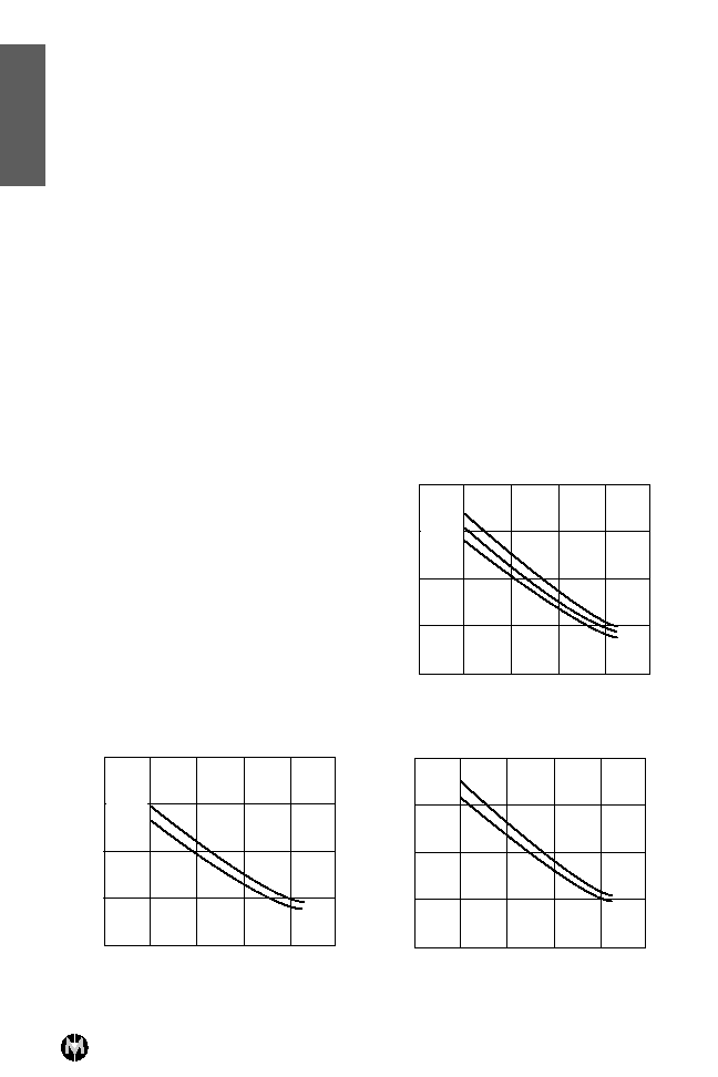
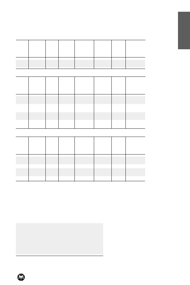
Typical Performance
MicroMetrics, Inc. 136 Harvey Road, Building C, Londonderry, NH 03053
Voice: 603-641-3800, Fax: 603-641-3500, Internet: www.micrometrics.com, E-mail: serv@micrometrics.com
.10
.01
.10
1.0
10
100
1.0
10
100
1000
MMN7028
MMN7036
MMN7026
SERIES RESIST
ANCE, R
S
(Ohms)
FORWARD BIAS CURRENT, If
(mA)
.10
.01
.10
1.0
10
100
1.0
10
100
1000
MMN7023
MMN7021
SERIES RESIST
ANCE, R
S
(Ohms)
FORWARD BIAS CURRENT, If
(mA)
.10
1.0
10
100
1000
SERIES RESIST
ANCE, R
S
(Ohms)
MMN7032
MMN7034
.01
.10
1.0
10
100
FORWARD BIAS CURRENT, If
(mA)
43
MicroMetrics, Inc. 136 Harvey Road, Building C, Londonderry, NH 03053
Voice: 603-641-3800, Fax: 603-641-3500, Internet: www.micrometrics.com, E-mail: serv@micrometrics.com
Control Devices: MMN 7000 Series
Electrical Characteristics
Ultra Fast Switching
Vbr
1
Cj-10 V
2
Tl
3
TS
4
Rs
5
@
Rs
5
@
jc
MIN
MAX
TYP
MAX
50 mA
10 mA
MAX
Part
(V)
(pF)
(nS)
(nS)
MAX
TYP
∞C/W
Number
(Ohms)
(Ohms)
25
.15
10
1.5
.55
.8
50
MMN7011
25
.25
10
1.5
.4
.6
35
MMN7013
Fast Switching, Low Power
Vbr
1
Cj-10 V
2
Tl
3
TS
4
Rs
5
@
Rs
5
@
jc
MIN
MAX
TYP
MAX
75 mA
20 mA
MAX
Part
(V)
(pF)
(nS)
(nS)
MAX
TYP
∞C/W
Number
(Ohms)
(Ohms)
70
.1
60
5
.7
1.0
70
MMN7021
70
.2
60
5
.5
.7
55
MMN7023
100
.07
100
10
.9
1.5
80
MMN7026
100
.15
100
10
.6
1.0
60
MMN7028
100
.3
100
15
.45
.8
50
MMN7030
200
.07
225
15
1.2
2.2
80
MMN7032
200
.15
225
15
.8
1.0
60
MMN7034
200
.3
225
15
.6
.7
50
MMN7036
Medium Power, General Purpose
Vbr
1
Cj-10 V
2
Tl
3
TS
4
Rs
5
@
Rs
5
@
jc
MIN
MAX
TYP
MAX
100 mA
20 mA
MAX
Part
(V)
(pF)
(nS)
(nS)
MAX
TYP
∞C/W
Number
(Ohms)
(Ohms)
200
.07
400
20
1.5
2.2
60
MMN7041
200
.15
400
20
1.0
1.9
50
MMN7043
200
.3
400
20
.7
1.4
40
MMN7045
200
.1
600
25
1.2
2.0
50
MMN7049
200
.2
600
25
.8
1.7
40
MMN7051
200
.5
600
25
.6
1.2
15
MMN7053
Contr
ol Devices
Notes:
1. Reverse Breakdown Voltage measured at 10 µA.
2. Junction Capacitance measured at -10 volts at 1 MHz.
3. Minority Carrier lifetime measured with IF = 10 mA, IR = 6mA.
4. RF Switching speed measured from 90% to 10% and 10% to 90% transmission. Drive output = +20 mA
and -4 volts, 200 mA spike with a rise time of 2 nS.
5. Series Resistance is measured at 1 GHz using transmission loss techniques.
Maximum Ratings
Operating Temperature
-55∞C to 150∞C
Storage Temperature
-65∞C to 200∞C
Reverse Breakdown
from 25 volts to 500 volts
Voltage (Vbr)
at 10 µA
Junction Capacitance (Cj-10)
from .07 pF to .5 pF at 10 volts
Switching Speed (Ts)
from 1 nS to 25 nS
Lifetime (Tl)
from 10 nS to 2.0 µS TYP
Chip Thickness
.004" - .007" thick
Continued on next page.