January 2000
1
LM4040/4041
LM4040/4041
Micrel
LM4040/4041
Precision Micropower Shunt Voltage Reference
General Description
Ideal for space critical applications, the LM4040 and LM4041
precision voltage references are available in the subminia-
ture (3mm
◊
1.3mm) SOT-23 surface-mount package.
The LM4040 is the available in fixed reverse breakdown
voltages of 2.500V, 4.096V and 5.000V. The LM4041 is
available with a fixed 1.225V or an adjustable reverse break-
down voltage.
The LM4040 and LM4041's advanced design eliminates the
need for an external stabilizing capacitor while ensuring
stability with any capacitive load, making them easy to use.
The minimum operating current ranges from 60
µ
A for the
LM4041-1.2 to 74
µ
A for the LM4040-5.0. LM4040 versions
have a maximum operating current of 15mA. LM4041
versions have a maximum operating current of 12mA.
The LM4040 and LM4041 utilizes zener-zap reverse break-
down voltage trim during wafer sort to ensure that the prime
parts have an accuracy of better than
±
0.1% (A grade) at
25
∞
C. Bandgap reference temperature drift curvature correc-
tion and low dynamic impedance ensure stable reverse
breakdown voltage accuracy over a wide range of operating
temperatures and currents.
Features
∑ Small SOT-23 package
∑ No output capacitor required
∑ Tolerates capacitive loads
∑ Fixed reverse breakdown voltages of 1.225, 2.500V,
4.096V and 5.000V
∑ Adjustable reverse breakdown version
∑ Contact Micrel for parts with extended temperature
range.
Key Specifications
∑ Output voltage tolerance (A grade, 25
∞
C) ..
±
0.1% (max)
∑ Low output noise (10Hz to 100Hz)
LM4040 ................................................ 35
µ
V
RMS
(typ)
LM4041 ................................................ 20
µ
V
RMS
(typ)
∑ Wide operating current range
LM4040 ................................................ 60
µ
A to 15mA
LM4041 ................................................ 60
µ
A to 12mA
∑ Industrial temperature range .................. ≠40
∞
C to +85
∞
C
∑ Low temperature coefficient ................ 100ppm/
∞
C (max)
Applications
∑ Battery-Powered Equipment
∑ Data Acquisition Systems
∑ Instrumentation
∑ Process Control
∑ Energy Management
∑ Product Testing
∑ Automotive Electronics
∑ Precision Audio Components
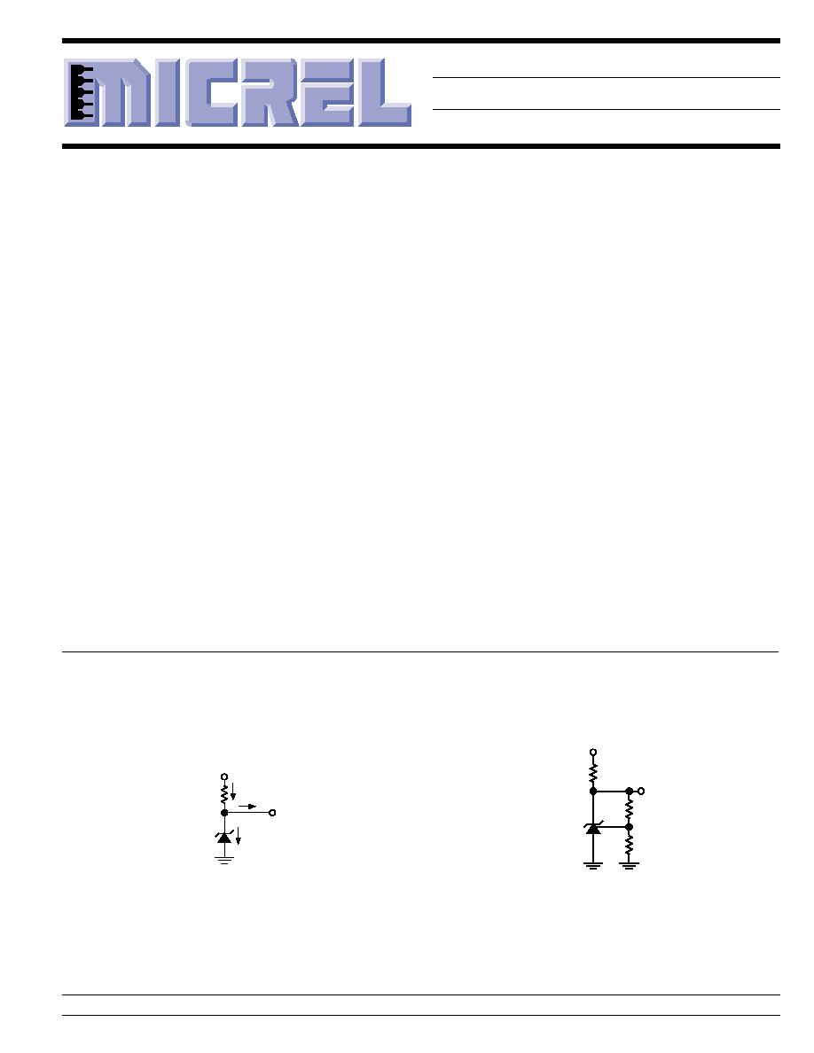
Typical Applications
V
S
R
S
V
R
LM4041
Adjustable
R
1
R
2
V
O
V
S
R
S
V
R
I
Q
+ I
L
I
Q
I
L
LM4040
LM4041
V
O
Figure 2. LM4041 Adjustable
Shunt Regulator Application
Figure 1. LM4040, LM4041 Fixed
Shunt Regulator Application
V
O
= 1.233 (R
2
/R
1
+ 1)
Micrel, Inc. ∑ 1849 Fortune Drive ∑ San Jose, CA 95131 ∑ USA ∑ tel + 1 (408) 944-0800 ∑ fax + 1 (408) 944-0970 ∑ http://www.micrel.com
LM4040/4041
Micrel
LM4040/4041
2
January 2000
Part Number *
Voltage
Accuracy,
Temp. Coefficient
LM4041AIM3-1.2
1.225V
±
0.1%, 100ppm/
∞
C
LM4041BIM3-1.2
1.225V
±
0.2%, 100ppm/
∞
C
LM4041CIM3-1.2
1.225V
±
0.5%, 100ppm/
∞
C
LM4041DIM3-1.2
1.225V
±
1.0%, 150ppm/
∞
C
LM4041CIM3-ADJ
1.24V to 10V
±
0.5%, 100ppm/
∞
C
LM4041DIM3-ADJ
1.24V to 10V
±
1.0%, 150ppm/
∞
C
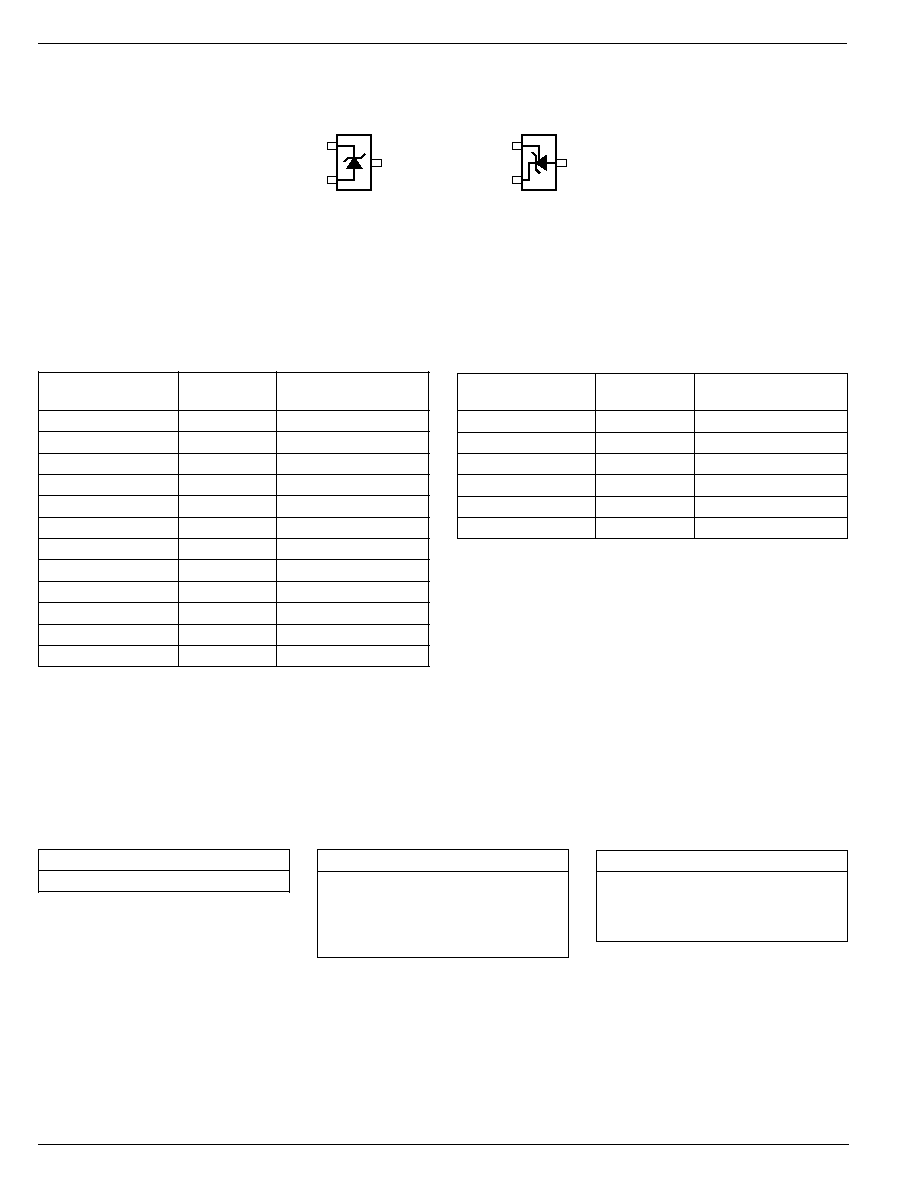
Pin Configuration
1
2
3 ≠
FB
+
Adjustable Version
SOT-23 (M3) Package
Top View
Fixed Version
SOT-23 (M3) Package
Top View
1
2
3
+
≠
Pin 3 must float or
be connected to pin 2.
Part Number *
Voltage
Accuracy,
Temp. Coefficient
LM4040AIM3-2.5
2.500V
±
0.1%, 100ppm/
∞
C
LM4040BIM3-2.5
2.500V
±
0.2%, 100ppm/
∞
C
LM4040CIM3-2.5
2.500V
±
0.5%, 100ppm/
∞
C
LM4040DIM3-2.5
2.500V
±
1.0%, 150ppm/
∞
C
LM4040AIM3-4.1
4.096V
±
0.1%, 100ppm/
∞
C
LM4040BIM3-4.1
4.096V
±
0.2%, 100ppm/
∞
C
LM4040CIM3-4.1
4.096V
±
0.5%, 100ppm/
∞
C
LM4040DIM3-4.1
4.096V
±
1.0%, 150ppm/
∞
C
LM4040AIM3-5.0
5.000V
±
0.1%, 100ppm/
∞
C
LM4040BIM3-5.0
5.000V
±
0.2%, 100ppm/
∞
C
LM4040CIM3-5.0
5.000V
±
0.5%, 100ppm/
∞
C
LM4040DIM3-5.0
5.000V
±
1.0%, 150ppm/
∞
C
Example
Field
Code
_ _ A
3rd Character
A =
±
0.1%
B =
±
0.2%
C =
±
0.5%
D =
±
1.0%
Example
Field
Code
_ 2 _
2nd Character 1 = 1.225V
2 = 2.500V
4 = 4.096V
5 = 5.000V
A = Adjustable
Example: R2C represents
Reference, 2.500V,
±
0.5% (LM4040CIM3-2.5)
Note: If 3rd character is omitted, container will
indicate tolerance.
SOT-23 Package Markings
Example
Field
Code
R _ _
1st Character
R = Reference
Ordering Information
January 2000
3
LM4040/4041
LM4040/4041
Micrel
Absolute Maximum Ratings
Reverse Current ......................................................... 20mA
Forward Current ......................................................... 10mA
Maximum Output Voltage
LM4041-Adjustable ................................................... 15V
Power Dissipation at T
A
= 25
∞
C (Note 2) ................ 306mW
Storage Temperature ............................... ≠65
∞
C to +150
∞
C
Lead Temperature
Vapor phase (60 seconds) .............................. +215
∞
C
Infrared (15 seconds) ...................................... +220
∞
C
ESD Susceptibility
Human Body Model (Note 3) ................................. 2kV
Machine Model (Note 3) ...................................... 200V
Operating Ratings
(Notes 1 and 2)
Temperature Range
(T
MIN
T
A
T
MAX
) .......................... ≠40
∞
C
T
A
+85
∞
C
Reverse Current
LM4040-2.5 .......................................... 60
µ
A to 15mA
LM4040-4.1 .......................................... 68
µ
A to 15mA
LM4040-5.0 .......................................... 74
µ
A to 15mA
LM4041-1.2 .......................................... 60
µ
A to 12mA
LM4041-ADJ ........................................ 60
µ
A to 12mA
Output Voltage Range
LM4041-ADJ .......................................... 1.24V to 10V
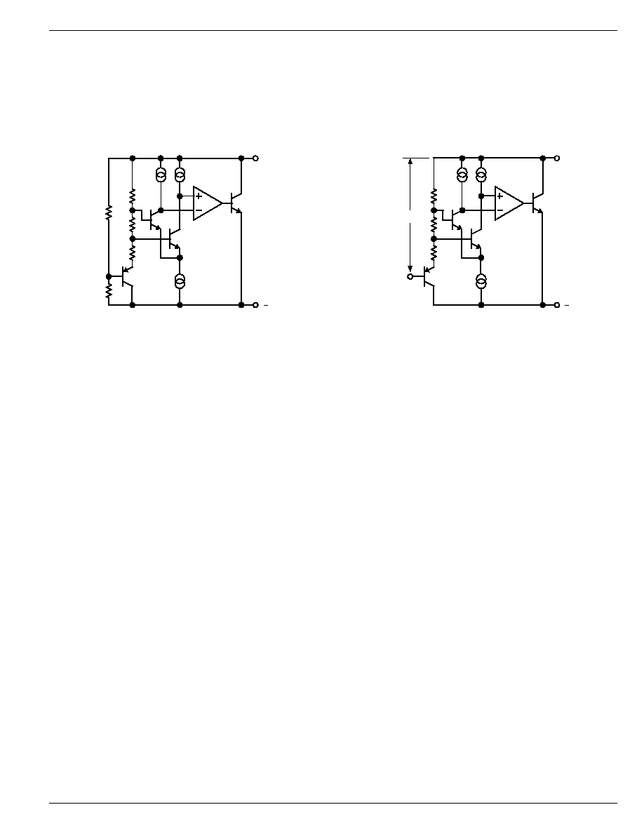
+
Functional Diagram
LM4040, LM4041 Fixed
Functional Diagram
LM4041 Adjustable
+
FB
V
REF

LM4040/4041
Micrel
LM4040/4041
4
January 2000
LM4040-2.5 Electrical Characteristics
Boldface limits apply for T
A
= T
J
= T
MIN
to T
MAX
; all other limits T
A
= T
J
= 25
∞
C. The grades A, B, C, and D designate initial Reverse
Breakdown Voltage tolerance of
±
0.1%,
±
0.2%,
±
0.5%, and
±
1.0 respectively.
LM4040AIM3 LM4040BIM3 LM4040CIM3
Symbol
Parameter
Conditions
Typical
Units
(Note 4)
Limits
Limits
Limits
(Limit)
(Note 5)
(Note 5)
(Note 5)
V
R
Reverse Breakdown Voltage
I
R
= 100
µ
A
2.500
V
Reverse Breakdown Voltage
I
R
= 100
µ
A
±
2.5
±
5.0
±
12
mV (max)
Tolerance
±
19
±
21
±
29
mV (max)
I
RMIN
Minimum Operating Current
45
µ
A
60
60
60
µ
A (max)
65
65
65
µ
A (max)
V
R
/
T
Average Reverse Breakdown
I
R
= 10mA
20
ppm/
∞
C
Voltage Temperature
I
R
= 1mA
15
100
100
100
ppm/
∞
C (max)
Coefficient
I
R
= 100
µ
A
15
ppm/
∞
C (max)
V
R
/
I
R
Reverse Breakdown Voltage
I
RMIN
I
R
1mA
0.3
mV
Change with Operating
0.8
0.8
0.8
mV (max)
Current Change
1.0
1.0
1.0
mV (max)
1mA
I
R
15mA
2.5
mV
0.6
0.6
0.6
mV (max)
8.0
8.0
8.0
mV (max)
Z
R
Reverse Dynamic Impedance
I
R
= 1mA, f = 120Hz
0.3
I
AC
= 0.1 I
R
0.8
0.8
0.9
(max)
e
N
Wideband Noise
I
R
= 100
µ
A
10Hz
f
10kHz
35
µ
V
RMS
V
R
Reverse Breakdown Voltage
t = 1000hrs
Long Term Stability
T = 25
∞
C
±
0.1
∞
C
120
ppm
I
R
= 100
µ
A
LM4040DIM3
Symbol
Parameter
Conditions
Typical
Units
(Note 4)
Limits
(Limit)
(Note 5)
V
R
Reverse Breakdown Voltage
I
R
= 100
µ
A
2.500
V
Reverse Breakdown Voltage
I
R
= 100
µ
A
±
25
mV (max)
Tolerance
±
49
mV (max)
I
RMIN
Minimum Operating Current
45
µ
A
65
µ
A (max)
70
µ
A (max)
V
R
/
T
Average Reverse Breakdown
I
R
= 10mA
20
ppm/
∞
C
Voltage Temperature
I
R
= 1mA
15
150
ppm/
∞
C (max)
Coefficient
I
R
= 100
µ
A
15
ppm/
∞
C (max)
V
R
/
I
R
Reverse Breakdown Voltage
I
RMIN
I
R
1mA
0.3
mV
Change with Operating
1.0
mV (max)
Current Change
1.2
mV (max)
1mA
I
R
15mA
2.5
mV
8.0
mV (max)
10.0
mV (max)
Z
R
Reverse Dynamic Impedance
I
R
= 1mA, f = 120Hz
0.3
I
AC
= 0.1 I
R
1.1
(max)
e
N
Wideband Noise
I
R
= 100
µ
A
10Hz
f
10kHz
35
µ
V
RMS
V
R
Reverse Breakdown Voltage
t = 1000hrs
Long Term Stability
T = 25
∞
C
±
0.1
∞
C
120
ppm
I
R
= 100
µ
A

January 2000
5
LM4040/4041
LM4040/4041
Micrel
LM4040-4.1 Electrical Characteristics
Boldface limits apply for T
A
= T
J
= T
MIN
to T
MAX
; all other limits T
A
= T
J
= 25
∞
C. The grades A, B, C, and D designate initial Reverse
Breakdown Voltage tolerance of
±
0.1%,
±
0.2%,
±
0.5%, and
±
1.0% respectively.
LM4040AIM3
LM4040BIM3
Symbol
Parameter
Conditions
Typical
Units
(Note 4)
Limits
Limits
(Limit)
(Note 5)
(Note 5)
V
R
Reverse Breakdown Voltage
I
R
= 100
µ
A
4.096
V
Reverse Breakdown Voltage
I
R
= 100
µ
A
±
4.1
±
8.2
mV (max)
Tolerance
±
31
±
35
mV (max)
I
RMIN
Minimum Operating Current
50
µ
A
68
68
µ
A (max)
73
73
µ
A (max)
V
R
/
T
Average Reverse Breakdown
I
R
= 10mA
30
ppm/
∞
C
Voltage Temperature
I
R
= 1mA
20
100
100
ppm/
∞
C (max)
Coefficient
I
R
= 100
µ
A
20
ppm/
∞
C (max)
V
R
/
I
R
Reverse Breakdown Voltage
I
RMIN
I
R
1mA
0.5
mV
Change with Operating
0.9
0.9
mV (max)
Current Change
1.2
1.2
mV (max)
1mA
I
R
15mA
3.5
mV
7.0
7.0
mV (max)
10.0
10.0
mV (max)
Z
R
Reverse Dynamic Impedance
I
R
= 1mA, f = 120Hz
0.5
I
AC
= 0.1 I
R
1.0
1.0
(max)
e
N
Wideband Noise
I
R
= 100
µ
A
10Hz
f
10kHz
80
µ
V
RMS
V
R
Reverse Breakdown Voltage
t = 1000hrs
Long Term Stability
T = 25
∞
C
±
0.1
∞
C
120
ppm
I
R
= 100
µ
A
LM4040CIM3
LM4040DIM3
Symbol
Parameter
Conditions
Typical
Units
(Note 4)
Limits
Limits
(Limits)
(Note 5)
(Note 5)
V
R
Reverse Breakdown Voltage
I
R
= 100
µ
A
4.096
V
Reverse Breakdown Voltage
I
R
= 100
µ
A
±
20
±
41
mV (max)
Tolerance
±
47
±
81
mV (max)
I
RMIN
Minimum Operating Current
50
µ
A
68
73
µ
A (max)
73
78
µ
A (max)
V
R
/
T
Average Reverse Breakdown
I
R
= 10mA
30
ppm/
∞
C
Voltage Temperature
I
R
= 1mA
20
100
150
ppm/
∞
C (max)
Coefficient
I
R
= 100
µ
A
20
ppm/
∞
C (max)
V
R
/
I
R
Reverse Breakdown Voltage
I
RMIN
I
R
1mA
0.5
mV
Change with Operating
0.9
1.2
mV (max)
Current Change
1.2
1.5
mV (max)
1mA
I
R
15mA
3.0
mV
7.0
9.0
mV (max)
10.0
13.0
mV (max)
Z
R
Reverse Dynamic Impedance
I
R
= 1mA, f = 120Hz
0.5
I
AC
= 0.1 I
R
1.0
1.3
(max)
e
N
Wideband Noise
I
R
= 100
µ
A
10Hz
f
10kHz
80
µ
V
RMS
V
R
Reverse Breakdown Voltage
t = 1000hrs
Long Term Stability
T = 25
∞
C
±
0.1
∞
C
120
ppm
I
R
= 100
µ
A