 | –≠–ª–µ–∫—Ç—Ä–æ–Ω–Ω—ã–π –∫–æ–º–ø–æ–Ω–µ–Ω—Ç: MIC4682 | –°–∫–∞—á–∞—Ç—å:  PDF PDF  ZIP ZIP |
October 2003
1
M0334-102203
MIC4682
Micrel
MIC4682
Precision Current Limit SO-8 SuperSwitcherTM Buck Regulator
Micrel, Inc. ∑ 1849 Fortune Drive ∑ San Jose, CA 95131 ∑ USA ∑ tel + 1 (408) 944-0800 ∑ fax + 1 (408) 944-0970 ∑ http://www.micrel.com
General Description
The MIC4682 is an easy-to-use step-down (buck) switch-
mode voltage regulator. It features a programmable current
limit that allows 10% current limit accuracy over its full
operating temperature range. The precision current limit
makes the MIC4682 ideal for constant-voltage constant-
current applications, such as simple battery chargers. The
precision current limit also gives designers the ability to set
the maximum output current below the saturation current
rating of the inductor. This allows the use of the smallest
possible inductors for a given application, saving valuable
space and cost.
The MIC4682 is a very robust device. Its 4V to 34V input
voltage range allows the MIC4682 to safely be used in
applications where voltage transients may be present. Addi-
tional protection features include cycle-by-cycle current lim-
iting and over-temperature shutdown. The MIC4682 is avail-
able in a thermally optimized power SO-8 package that allows
it to achieve 2A of continuous output current.
The MIC4682 requires a minimum number of external com-
ponents and can operate using a standard series of induc-
tors. Compensation is provided internally for fast transient
response and ease of use. The MIC4682 is available in the 8-
lead power SOP with a ≠40
∞
C to +125
∞
C junction tempera-
ture range.
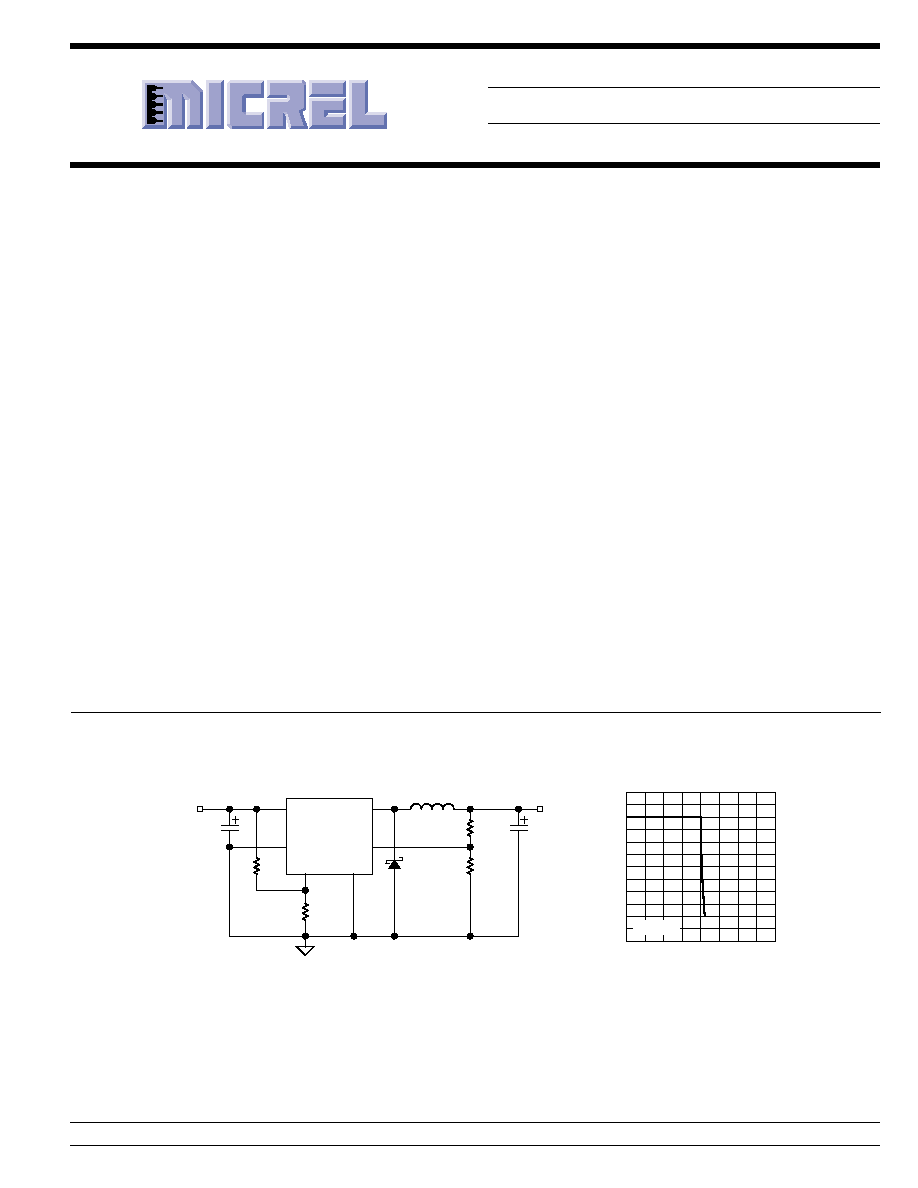
Typical Application
SW
L1
68
µ
H
IN
FB
ISET
SHDN
C2
220
µ
F
10V
R1
3.01k
R3
10M
R4
16.2k
R2
976
5V/1A
MIC4682
C1
10
µ
F
50V
(x2)
+7.5V to +34V
2, 6, 7
1
8
5
4
D1
B240
GND
3
0
1
2
3
4
5
6
0
0.5
1
1.5
2
OUTPUT VOLTAGE (V)
CURRENT LIMIT (A)
MIC4682 Current Limit
Characteristics
V
IN
= 12V
Constant Current/Constant Voltage Li Ion Battery Charger
Features
∑ Programmable output current limit
∑ 10% accuracy over temperature
∑ Wide 4V to 34V operating input voltage range
∑ Fixed 200kHz PWM operation
∑ Power SO-8 package allows 2A continuous output
current
∑ All surface mount solution
∑ Internally compensated
∑ Less than 1
µ
A typical shutdown-mode current
∑ Thermal shutdown protection
Applications
∑ Battery chargers
∑ White LED drivers
∑ Constant voltage constant current step-down converters
∑ Simple step-down regulator with precise current limit
∑ USB power supplies
SuperSwitcher is a trademark of Micrel, Inc.
MIC4682
Micrel
October 2003
2
M0334-102203
Ordering Information
Part Number
Voltage
Junction Temp. Range
Package
MIC4682BM
Adjustable
≠40
∞
C to +125
∞
C
8-lead SOP
Pin Description
Pin Number
Pin Name
Pin Function
1
FB
Feedback (Input): Output voltage sense node. Connect to 1.23V-tap of the
output voltage-divider network.
2, 6, 7
GND
Ground (Return): Ground
3
ISET
Current Limit Set (Input): Connect an external resistor to ground to set the
current limit. Do not ground or float this pin.
4
SHDN
Shutdown (Input): Logic low (<0.8V) enables regulator. Logic high (>2V)
shuts down regulator.
5
IN
Supply Voltage (Input): Unregulated +4V to +34V supply voltage.
8
SW
Switch (Output): Internal power emitter of NPN output switch.
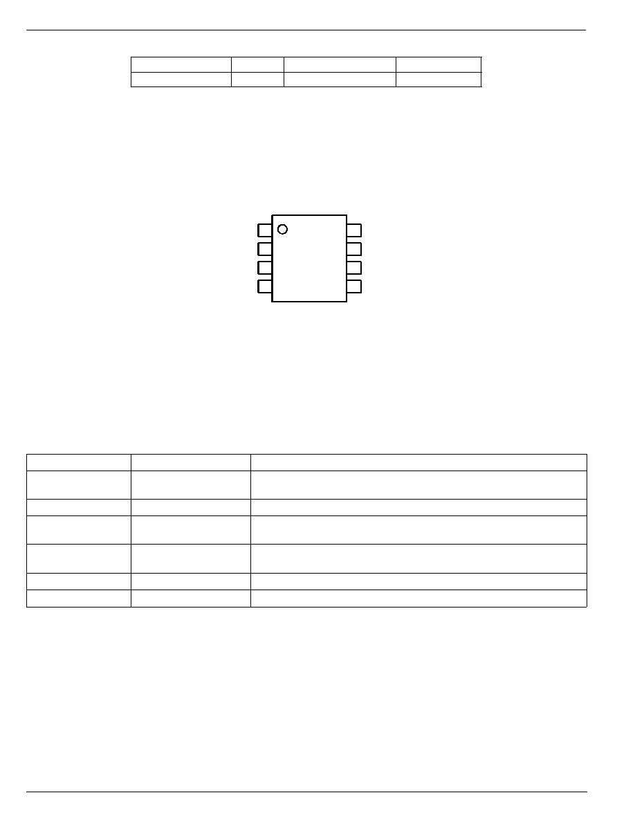
Pin Configuration
1
FB
GND
ISET
SHDN
8
SW
GND
GND
IN
7
6
5
2
3
4
Power SOP-8 (M)
October 2003
3
M0334-102203
MIC4682
Micrel
Absolute Maximum Ratings
(Note 1)
Supply Voltage (V
IN
), Note 3 ........................................ 38V
Shutdown Voltage (V
SHDN
) .......................... ≠0.3V to +38V
Steady-State Output Switch Voltage (V
SW
) .................. ≠1V
Feedback Voltage (V
FB
) ................................................ 12V
Current Limit Set Voltage (V
ISET
) ..................... 1.23V to 7V
Ambient Storage Temperature (T
S
) ......... ≠65
∞
C to +150
∞
C
ESD Rating, Note 5 ...................................................... 2kV
Electrical Characteristics
V
IN
= 12V; I
OUT
=500mA; R
ISET
= 16.2k (1A current limit); T
J
= 25
∞
C, bold values indicate ≠40
∞
C
T
J
+125
∞
C; unless otherwise noted.
Symbol
Parameter
Condition
Min
Typ
Max
Units
V
IN
Supply Voltage Range
Note 4
4
34
V
I
IN
Quiescent Current
V
FB
= 1.5V
7
12
mA
I
IN
Standby Quiescent Current
V
SHDN
= 5V (Regulator off)
35
100
µ
A
V
SHDN
= V
IN
1
µ
A
V
FB
Feedback Voltage
(
±
1%)
1.217
1.230
1.243
V
(
±
2%)
1.205
1.255
V
8V
V
IN
34V, 0.1A
I
LOAD
0.8A
1.193
1.230
1.267
V
1.180
1.280
V
I
LIM
Current Limit Accuracy, Note 7
See Test Circuit, V
OUT
= 3.6V
0.90
1
1.10
A
f
SW
Oscillator Frequency
180
200
220
kHz
D
MAX
Maximum Duty Cycle
V
FB
= 1.0V
93
95
%
V
SW
Switch Saturation Voltage
I
OUT
= 1A
1.4
1.8
V
I
SW
Switch Leakage Current
V
IN
= 34V, V
SHDN
= 5V, V
SW
= 0V
2
100
µ
A
V
IN
= 34V, V
SHDN
= 5V, V
SW
= ≠1V
2
10
mA
V
SHDN
Shutdown Input Logic Level
Regulator Off
2
1.4
V
Regulator On
1.25
0.8
V
I
SHDN
Shutdown Input Current
V
SHDN
= 5V (Regulator Off)
≠10
≠0.5
1
µ
A
V
SHDN
= 0V (Regulator On)
≠10
≠1.5
1
µ
A
T
J
Thermal Shutdown
160
∞
C
Note 1. Exceeding the absolute maximum rating may damage the device.
Note 2. This device is not guaranteed to operate beyond its specified operating rating.
Note 3. Absolute maximum rating is intended for voltage transients only; prolonged DC operation is not recommended.
Note 4. V
IN(MIN)
= V
OUT
+ 2.5V or 4V whichever is greater.
Note 5. Devices are ESD sensitive. Handling precautions recommended. Human body model, 1.5k
in series with 100pF.
Note 6. Measured on 1.5" square of 1oz. copper FR4 printed circuit board connected to the device ground leads.
Note 7. Short circuit protection is guaranteed to V
IN
= 30V max.
Operating Ratings
(Note 2)
Supply Voltage (V
IN
) Note 4 and 7 ..................... 4V to 34V
Junction Temperature Range (T
J
) ........... ≠40
∞
C to +125
∞
C
Package Thermal Impedance
JA
SOP-8, Note 6 .............................................. 63
∞
C/W
JC
SOP-8, Note 6 .............................................. 20
∞
C/W
MIC4682
Micrel
October 2003
4
M0334-102203
Test Circuit
SW
L1
68
µ
H
IN
FB
ISET
SHDN
C2
220
µ
F
10V
R1
3.01k
R3
10M
R2
976
MIC4682
C1 (x2)
10
µ
F
50V
V
IN
R
ISET
V
OUT
2, 6, 7
1
8
5
4
D1
B240A
GND
3
Current Limit Test Circuit
OUTPUT V
O
L
T
A
GE
(V)
OUTPUT CURRENT (A)
0
5.0
3.6
10%
1.10
0.90
Constant-Current Constant-Voltage Accuracy
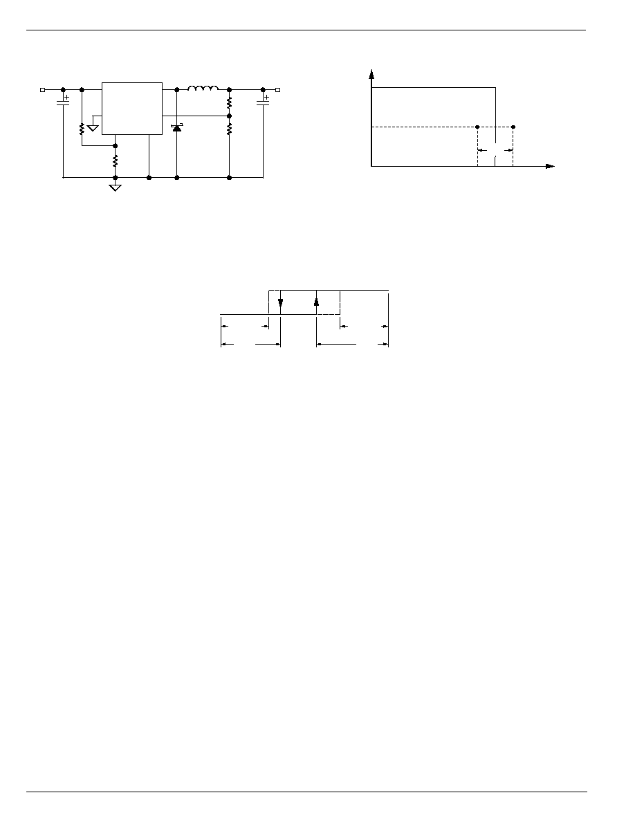
Shutdown Input Behavior
OFF
ON
GUARANTEED
OFF
TYPICAL
OFF
GUARANTEED
ON
TYPICAL
ON
0.8V
1.25V
0V
1.4V
V
IN(max)
2V
Shutdown Hysteresis
October 2003
5
M0334-102203
MIC4682
Micrel
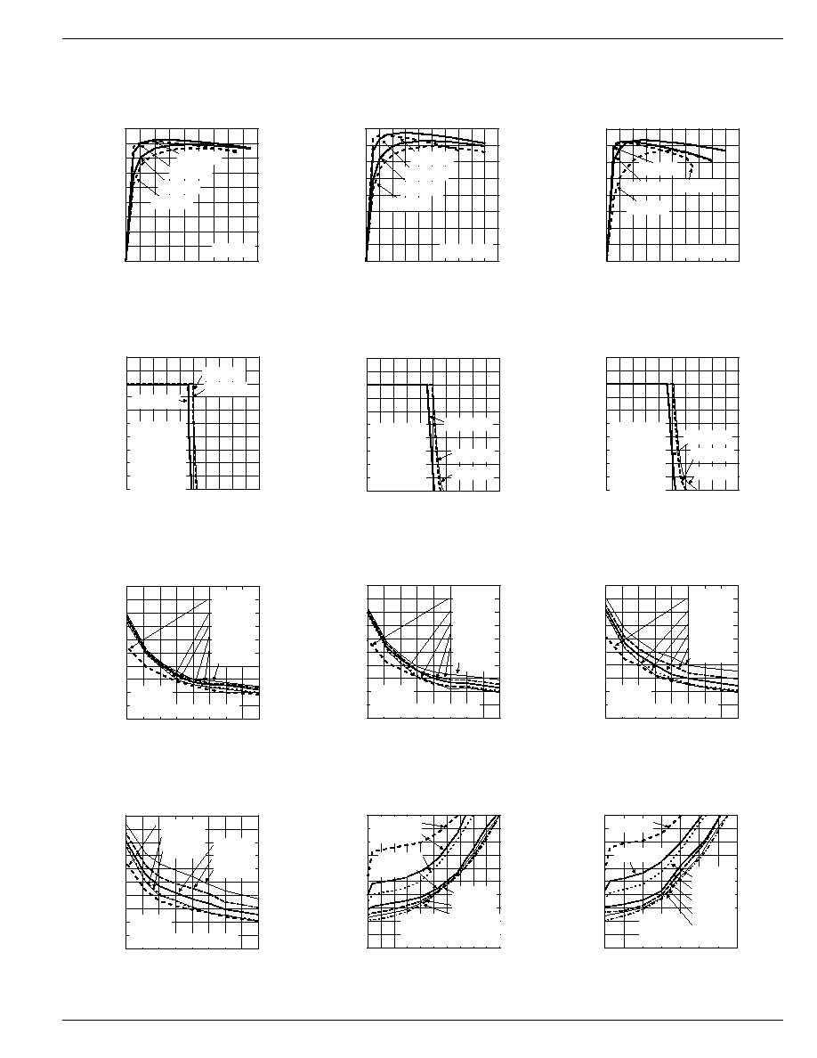
Typical Characteristics
T
A
= 25
∞
C unless otherwise noted.
0
10
20
30
40
50
60
70
80
90
0
0.4
0.8
1.2
1.6
EFFICIENCY (%)
OUTPUT CURRENT (A)
Efficiency
vs. Output Current
V
OUT
= 5V
V
IN
= 7.5V
V
IN
= 12V
V
IN
= 24V
V
IN
= 30V
0
10
20
30
40
50
60
70
80
0
0.4
0.8
1.2
1.6
2
EFFICIENCY (%)
OUTPUT CURRENT (A)
Efficiency
vs. Output Current
V
OUT
= 3.3V
V
IN
= 5.8V
V
IN
= 12V
V
IN
= 24V
V
IN
= 30V
0
10
20
30
40
50
60
70
80
0
0.4
0.8
1.2
1.6
2
EFFICIENCY (%)
OUTPUT CURRENT (A)
Efficiency
vs. Output Current
V
OUT
= 2.5V
V
IN
= 5V
V
IN
= 6V
V
IN
= 12V
V
IN
= 30V
1
2
3
4
5
6
0
0.4
0.8
1.2
1.6
2
OUTPUT VOLTAGE (V)
CURRENT LIMIT (A)
Output Voltage
vs. Current Limit
V
IN
= 12V
R
ISET
= 16.2k
Load =
Continuous
L = 68
µ
H
R3 = 10M
T
A
= ≠40
∞
C
T
A
= 25
∞
C
T
A
= 60
∞
C
1
2
3
4
5
6
0
0.4
0.8
1.2
1.6
2
OUTPUT VOLTAGE (V)
CURRENT LIMIT (A)
Output Voltage
vs. Current Limit
V
IN
= 24V
R
ISET
= 16.2k
Load =
Continuous
L = 68
µ
H
R3 = 10M
T
A
= ≠40
∞
C
T
A
= 25
∞
C
T
A
= 60
∞
C
1
2
3
4
5
6
0
0.4
0.8
1.2
1.6
2
OUTPUT VOLTAGE (V)
CURRENT LIMIT (A)
Output Voltage
vs. Current Limit
V
IN
= 30V
R
ISET
= 16.2k
Load =
Continuous
L = 68
µ
H
R3 = 10M
T
A
= ≠40
∞
C
T
A
= 25
∞
C
T
A
= 60
∞
C
0
0.2
0.4
0.6
0.8
1
1.2
1.4
1.6
1.8
2
10 15 20 25 30 35 40 45 50
CURRENT LIMIT (A)
R
ISET
(k
)
Current Limit
vs. R
ISET
at T
J
= ≠40
∞
C
V
IN
= 4V
V
IN
= 5V
V
IN
= 12V
V
IN
= 24V
V
IN
= 30V
V
IN
= 34V
L = 68
µ
H
R3 = 10M
V
OUT
= 1.0V (Pulsed Load)
0
0.2
0.4
0.6
0.8
1
1.2
1.4
1.6
1.8
2
10 15 20 25 30 35 40 45 50
CURRENT LIMIT (A)
R
ISET
(k
)
Current Limit
vs. R
ISET
at T
J
= 25
∞
C
V
IN
= 4V
V
IN
= 5V
V
IN
= 12V
V
IN
= 24V
V
IN
= 30V
V
IN
= 34V
L = 68
µ
H
R3 = 10M
V
OUT
= 1.0V (Pulsed Load)
0
0.2
0.4
0.6
0.8
1
1.2
1.4
1.6
1.8
2
10 15 20 25 30 35 40 45 50
CURRENT LIMIT (A)
R
ISET
(k
)
Current Limit
vs. R
ISET
at T
J
= 85
∞
C
V
IN
= 4V
V
IN
= 5V
V
IN
= 12V
V
IN
= 24V
V
IN
= 30V
V
IN
= 34V
L = 68
µ
H
R3 = 10M
V
OUT
= 1.0V (Pulsed Load)
0
0.2
0.4
0.6
0.8
1
1.2
1.4
1.6
1.8
2
10 15 20 25 30 35 40 45 50
CURRENT LIMIT (A)
R
ISET
(k
)
Current Limit
vs. R
ISET
at T
J
= 125
∞
C
V
IN
= 4V
V
IN
= 5V
V
IN
= 12V
L = 68
µ
H
R3 = 10M
V
OUT
= 1.0V (Pulsed Load)
V
IN
= 24V
V
IN
= 30V
V
IN
= 34V
0
0.2
0.4
0.6
0.8
1
1.2
1.4
1.6
1.8
2
4
8
12
16
20
24
28
32
SHORT CIRCUIT CURRENT LIMIT (A)
INPUT VOLTAGE (V)
Short Circuit Current Limit
vs. Input Voltage
at T
J
= 25
∞
C
L = 68
µ
H
R3 = 10M
V
OUT
~0V (Pulsed Load)
R
ISET
=20k
R
ISET
=25k
R
ISET
=30k
R
ISET
=40k
R
ISET
=50k
R
ISET
=10k
R
ISET
=15.8k
0
0.2
0.4
0.6
0.8
1
1.2
1.4
1.6
1.8
2
4
7 10 13 16 19 22 25 28 31 34
SHORT CIRCUIT CURRENT LIMIT (A)
INPUT VOLTAGE (V)
Short Circuit Current Limit
vs. Input Voltage
at T
J
= ≠40
∞
C
R
ISET
=20k
L = 68
µ
H
R3 = 10M
V
OUT
~0V (Pulsed Load)
R
ISET
=30k
R
ISET
=40k
R
ISET
=50k
R
ISET
=10k
R
ISET
=15.8k
R
ISET
=25k