May 2003
1
MIC809-5
MIC809-5
Micrel
MIC809-5
Microprocessor Reset Circuit
Final Information
General Description
The MIC809-5 is a power supply supervisor that provides
under-voltage monitoring and power-on reset generation in
an industry standard 3-pin SOT package and pinout. The
reset output is asserted at power-on and any time the input
voltage drops below the programmed threshold. It remains
asserted for 30ms (min.) after the input subsequently rises
back above the threshold boundary. The MIC809-5 has an
active-low reset output.
The MIC809-5 is inherently immune to brief power supply
transients. Typical supply current is a low 6
µA. For those
applications that require a manual reset function, see the
MIC811/812. For those applications that require a longer
reset timeout, see the MIC809/810. (The MIC809-5 is iden-
tical to the industry-standard MIC809 with the exception of a
shorter reset timout.)
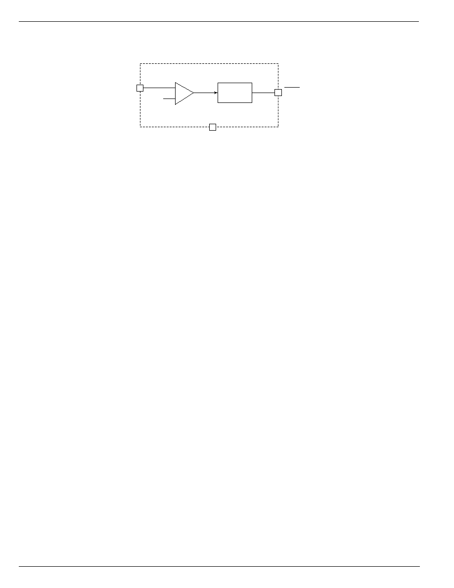
Typical Application
VCC
/RESET
µP
/RESET
MIC809-5
VCC
V
CC
Features
∑ Under-voltage monitor
∑ Power-on reset generation (30ms minimum)
∑ Choice of threshold voltages
∑ Active-low reset output
∑ No external components required
∑ Rejects brief input transients
∑ Industry standard package and pinout
∑ 3-pin IttyBittyTM SOT23-3 package
Applications
∑ PDAs, hand-held PCs
∑ Embedded controllers
∑ Telecommunications systems
∑ Power supplies
∑ Wireless/cellular systems
∑ Networking hardware
Micrel, Inc. ∑ 1849 Fortune Drive ∑ San Jose, CA 95131 ∑ USA ∑ tel + 1 (408) 944-0800 ∑ fax + 1 (408) 944-0970 ∑ http://www.micrel.com
Ordering Information
Typical
Nominal
Application Threshold
t
RST
Operating
Package
Part Number
Marking
Voltage*
Voltage
(ms)
Temp. Range
MIC809-5S-U
IX
3.3V
±5%
2.93
30
≠40
∞C to +85∞C SOT23-3
*Other voltages available. Contact Micrel for details. Minimum order may apply.
IttyBitty is a trademark of Micrel, Inc.
MIC809-5
Micrel
MIC809-5
2
May 2003
Pin Description
Pin Number
Pin Name
Pin Function
1
GND
Ground return for all IC functions.
2
/RESET
Digital Output. Active-low. Asserted whenever V
CC
falls below the threshold
voltage. It will remain asserted for no less than 30ms and be de-asserted
after V
CC
returns above the threshold.
3
VCC
Analog Input. Power supply input to the IC.
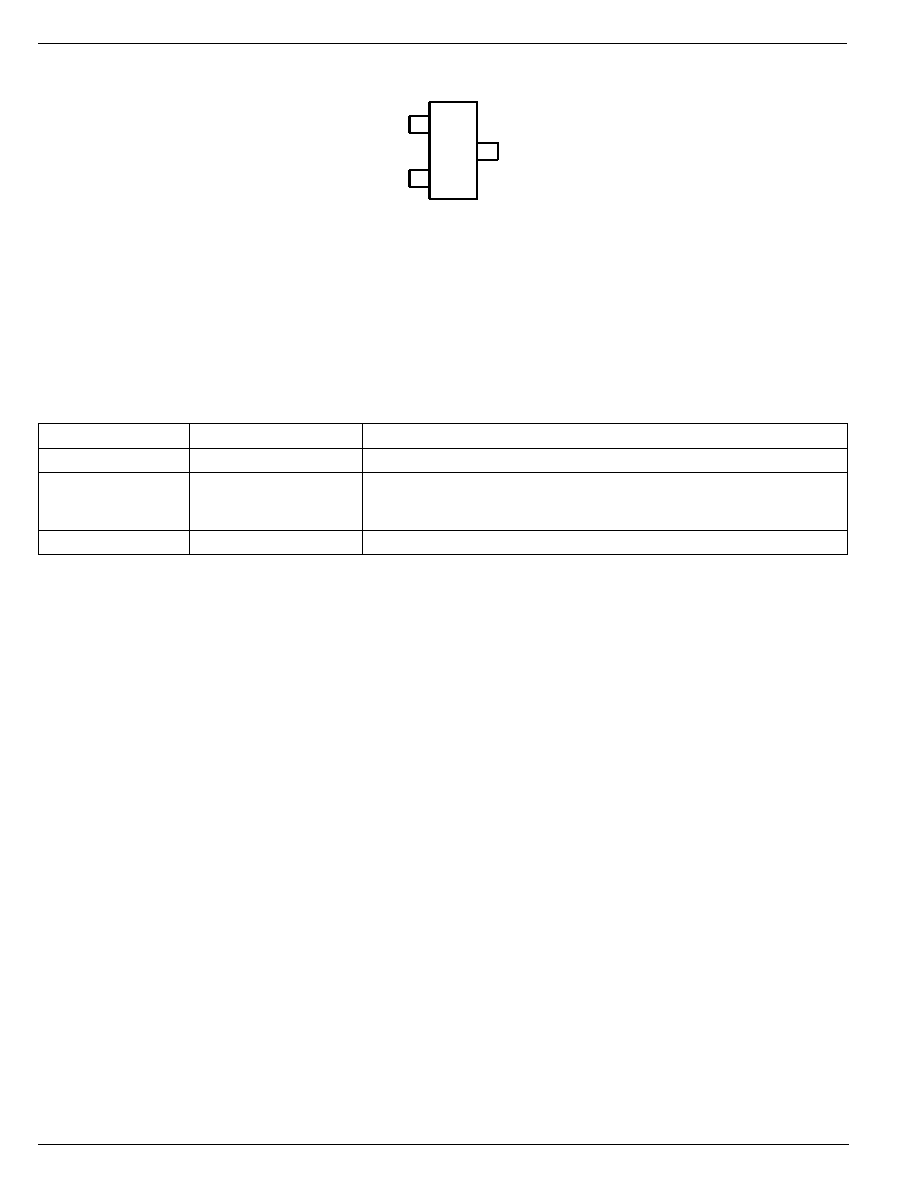
Pin Configuration
1
GND
/RESET
VCC
3
2
MIC809-5
3-Lead SOT23

May 2003
3
MIC809-5
MIC809-5
Micrel
Absolute Maximum Ratings
(Note 1)
Terminal Voltage (V
CC
) ............................... ≠0.3V to +6.0V
Input Current (V
CC
) .................................................... 20mA
Output Current (/RESET, RESET) ............................. 20mA
Lead Temperature (soldering, 10 sec.) ..................... 300
∞C
Storage Temperature (T
S
) ......................... ≠65
∞C to 150∞C
Rate of Rise (V
CC
) ................................................. 100V/
µs
ESD Rating, Note 3
Operating Ratings
(Note 2)
Ambient Temperature (T
A
) ......................... ≠40
∞C to +85∞C
Power Dissipation (T
A
= +70
∞C).............................. 320mW
Electrical Characteristics
For typical values, V
CC
= 3.3V, T
A
= 25
∞C; bold are for ≠40∞C to +85∞C; unless otherwise noted
Symbol
Parameter
Condition
Min
Typ
Max
Units
V
CC
Operating Voltage Range
T
A
= 0
∞C to 70∞C
1.4
5.5
V
T
A
= ≠40
∞C to 85∞C
1.6
5.5
V
I
CC
Supply Current
V
CC
< 3.6V
6
10
µA
V
TH
Reset Voltage Threshold
S Voltage Options
2.85
2.93
3.00
V
V
HYST
Typical hysteresis
5
mV
t
RST
Reset Timeout Period
30
66
ms
t
PROP
Propogation delay
/RESET < V
OL
, 100mV Overdrive
9.3
µs
V
OH
/RESET Output Voltage High
I
SOURCE
= 500
µA
0.8
◊◊
◊◊
◊V
CC
V
V
OL
/RESET Output Voltage Low
V
CC
= V
TH
min., I
SINK
= 1.2mA
0.3
V
V
CC
> 1.4V, I
SINK
= 50
µA, T
A
= 0
∞C to +70∞C
0.3
V
V
CC
> 1.6V, I
SINK
= 50
µA, T
A
= ≠40
∞ to +85∞C
0.3
V
Note 1.
Exceeding the absolute maximum rating may damage the device.
Note 2.
The device is not guaranteed to function outside its operating rating.
Note 3.
Devices are ESD sensitive. Handling precautions recommended. Human body model, 1.5k in series with 100pF.
Timing Diagram
/RESET
V
CC
V
TH
V
TH
t
RST
t
RST
Reset Timing Diagram

May 2003
5
MIC809-5
MIC809-5
Micrel
Applications Information
Microprocessor Reset
The /RESET pin is asserted whenever V
CC
falls below the
reset threshold voltage. The /RESET pin remains asserted
for a period of 30ms after V
CC
has risen above the reset
threshold voltage. The reset function ensures the micropro-
cessor is properly reset and powers up in a known condition
after a power failure. /RESET will remain valid with V
CC
as low
as 1.4V.
Transients on V
CC
The MIC809-5 is inherently immune to very short "glitches" on
V
CC
. In the case of very brief transients, V
CC
may drop below
the under-voltage threshold without triggering a reset. As
shown in the graph of Figure 1, the narrower the transient, the
deeper the threshold overdrive that will be ignored. The line
on the graph represents the typical allowable transient dura-
tion for a given amount of threshold overdrive that will
not
generate a reset. The data from which Figure 1 is derived was
taken by adding negative-going square-wave pulses to a DC
input voltage set at 0.5V above the actual measured thresh-
old for the part being characterized.
0
5
10
15
20
0
200
400
600
MAX. TRANSIENT DURATION (
µ
s)
RESET COMP. OVERDRIVE, V
TH
≠V
CC
(mV)
Typical Transient
Response
V
TH
= 2.932
Figure 1. Comparator Overdrive
vs. Duration
Ensuring Proper Operation at Low V
CC
At levels of V
CC
below 1.4V, the MIC809-5's output driver
cannot always turn on sufficiently to produce a valid logic-low.
In this situation, other circuits driven by /RESET could be
allowed to float, causing undesired operation. (In most cases,
however, it is expected that the circuits driven by the MIC809-
5 will be similarly inoperative at V
CC
=1.4V.)
If a given application requires that /RESET be valid below
V
CC
=1.4V, this can be accomplished by adding a pull-down
resistor to the output. A value of 100k
is recommended, as
this is usually an acceptable compromise of leakage current
and pull-down current. The resistor's value is not critical,
however. See Figure 2.
/RESET
/RESET INPUT
Microcontroller
or
Microprocessor
GND
100k
GND
V
IN
R
PULL-DOWN
V
CC
V
CC
MIC809
Figure 2. Ensuring a Valid
/RESET Signal at Low Voltage
Interfacing to Processors with Bidirectional Reset Pins
Some microprocessors have reset signal pins that are bidi-
rectional, rather than input only. The Motorola 68HC11 family
is one example. To prevent excessive current flow when the
processor asserts its reset output, a series resistor is em-
ployed between the MIC809-5's output and the reset pin. This
limits the current that will flow between the MIC809-5 and the
reset pin to a theoretical maximum of V
CC
/R
SERIES
. Because
this resistor also limits the drive capability of the supervisor's
output, a buffer may be required to drive additional circuitry.
See Figure 3.
4.7k
BUFFER
RESET SIGNAL
to OTHER CIRCUITS
V
CC
/RESET
GND
V
IN
MIC809
RESET I/O
Microcontroller
or
Microprocessor
GND
V
CC
Figure 3. Interfacing to Processors
with Bidirectional Reset Pins