 | –≠–ª–µ–∫—Ç—Ä–æ–Ω–Ω—ã–π –∫–æ–º–ø–æ–Ω–µ–Ω—Ç: MIC9131BM | –°–∫–∞—á–∞—Ç—å:  PDF PDF  ZIP ZIP |
July 2001
1
MIC9131
MIC9131
Micrel
MIC9131
High-Voltage, High-Speed Telecom DC-to-DC Controller
Final Information
General Description
The MIC9131 is a current-mode PWM controller that effi-
ciently converts ≠48V telecom voltages to logic levels. The
MIC9131 features a high voltage start-up circuit that allows
the device to be connected to input voltages as high as 180V.
The high input voltage capability protects the MIC9131 from
line transients that are common in telecom systems. The
start-up circuitry also saves valuable board space and simpli-
fies designs by integrating several external components.
The MIC9131 is capable of high speed operation. Typically
the MIC9131 can control a sub-25ns pulse width on the gate
out pin. Its internal oscillator can operate over 2.5MHz, with
even higher frequencies available through synchronisation.
The high speed operation of the MIC9131 is made safe by the
very fast, 34ns response from current sense to output,
minimizing power dissipation in a fault condition.
The MIC9131 allows for the designs of high efficiency power
supplies. It can achieve efficiencies over 90% at high output
currents. Its low 1.3mA quiescent current allows high effi-
ciency even at light loads.
The MIC9131 has a maximum duty cycle of 75%. For designs
requiring a maximum duty cycle of 50%, refer to the MIC9130.
The MIC9131 is available in a 16-pin SOP and 16-pin QSOP
package options. The junction temperature range is from
≠40
∞
C to +125
∞
C.
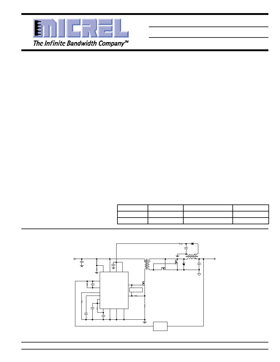
Typical Application
OUT
ISNS
FB
VBIAS
EN
RBIAS
AGND PGND
CPWR
UVLO
VCC
LINE
OSC
SS
COMP
2
1
13
10
8
4
16
14
7
6
3
12
9
11
15
MIC9131
VOUT
3.3V @ 20A
VIN
36V to 72V
12V
OPTO
FEEDBACK
Si4884DY
(x2)
Si4884DY
(x2)
B320A
1.5
µ
H
100
µ
F
IRFS3IN20D
0.1
1W
270pF
2.61k
562k
10nF
1M
37.4k
1N5818
10
µ
F
25V
10
0.1
µ
F
10k
6:1
L = 530
µ
H
4:1
SYNC
5
SLOPE
COMPENSATION
0.1
µ
F
8.2k
90% Efficient Telecommunications Power Supply
Features
∑ Input voltages up to 180V
∑ Internal oscillator capable of > 2.5MHz operation
∑ Accurate 75% maximum duty cycle
∑ Synchronisation capability to 6MHz
∑ Current sense delay of 34ns
∑ Minimum pulse width of <25ns
∑ 90% efficiency
∑ 1.3mA quiescent current
∑ 1
µ
A shutdown current
∑ Soft-start
∑ Resistor programmable current sense threshold
∑ Selectable soft-start retry
∑ 4
sink, 12
source output driver
∑ Programmable under-voltage lockout
∑ Constant-frequency PWM current-mode control
∑ 16-pin SOIC and 16-pin QSOP
Applications
∑ Telecom power supplies
∑ Line cards
∑ ISDN network terminators
∑ Micro- and pico-cell base stations
∑ Low power (< 100W) dc-dc converters
∑ DSL line cards
Micrel, Inc. ∑ 1849 Fortune Drive ∑ San Jose, CA 95131 ∑ USA ∑ tel + 1 (408) 944-0800 ∑ fax + 1 (408) 944-0970 ∑ http://www.micrel.com
Ordering Information
Part Number
Max. Duty Cycle
Junction Temp. Range
Package
MIC9131BM
75%
≠40
∞
C to +125
∞
C
16-Pin SOP
MIC9131BQS
75%
≠40
∞
C to +125
∞
C
16-Pin QSOP
MIC9131
Micrel
MIC9131
2
July 2001
Pin Description
Pin Number
Pin Name
Pin Function
1
LINE
Line (Input): 180Vdc maximum supply input. May be floated if unused.
2
VCC
Supply (Input): MIC9131 internal supply input.
3
RBIAS
Bias Resistor (External Component): Connect 562K
to ground.
4
OSC
Oscillator RC Network (External Components): Connect external resistor-
capacitor network to set oscillator frequency.
5
SYNC
Synchronization (Input): External oscillator input for slave operation of
controller. See OSC. Do not float.
6
COMP
Compensation (External Components): Error amplifier output for external
compensation network connection.
7
FB
Feedback (Input): Error amplifier inverting input.
8
CPWR
Current Limit Selection (Input): When CPWR is high, an over-current
condition at the ISNS input will terminate the gate drive and reset the soft-
start latch. If the CPWR pin is low, an over-current condition at the ISNS
input will terminate the gate drive signal, but will not cause a reset of the
soft-start circuit.
9
VBIAS
Reference (Output): Internal 5V supply. Will source 5mA maximum.
10
EN
Enable (Input): Logic level enable/shutdown input; logic high = enabled (on),
logic low = shutdown (off).
11
AGND
Analog Ground (Return)
12
SS
Soft-Start (External Components): Connect external capacitor to slowly ramp
up duty cycle during startup and over-current conditions.
13
UVLO
Undervoltage Lockout (External Components): Connect to unbiased resistive
divider network to set controller's minimum operating voltage. Connect to
VBIAS if not needed.
14
ISNS
Current Sense (Input): Connect between external switching MOSFET source
and switch current sense resistor.
15
PGND
Power Ground (Return)
16
OUT
Switch Drive Output (Output): Connect to gate of external switching
MOSFET.
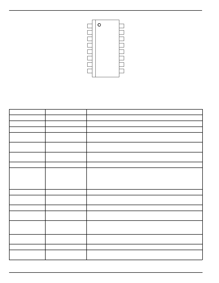
Pin Configuration
2
VCC
3
RBIAS
4
OSC
5
SYNC
6
COMP
7
FB
1
LINE
8
CPWR
OUT
16
PGND
15
ISNS
14
UVLO
13
SS
12
AGND
11
10
9 VBIAS
EN
16-Pin SOP (M)
16-Pin QSOP (QS)
July 2001
3
MIC9131
MIC9131
Micrel
Absolute Maximum Ratings
(Note 1)
Line Input Voltage (V
LINE
) ......................................... +190V
V
CC
Input Voltage (V
CC
) ............................................. +19V
Current Sense Input Voltage (V
ISNS
) ............. ≠0.3 to +5.3V
Enable Voltage (V
EN
) ............................ ≠0.3 to V
CC
+ 0.3V
Feedback Input Voltage (V
FB
) ........................ ≠0.3 to +5.3V
Sync Input Voltage (V
SYNC
) ........................... ≠0.3 to +5.3V
Soft-Start Voltage (V
SS
) ................................. ≠0.3 to +5.3V
UVLO Voltage (V
UVLO
) .................................. ≠0.3 to +5.3V
Storage Temperature (T
S
) ....................... ≠65
∞
C to +150
∞
C
Power Dissipation (P
D
) .......................................................
16-pin SOP .................................. 400mW @ T
A
= +85
∞
C
16-pin QSOP ............................... 245mW @ T
A
= +85
∞
C
ESD Rating, Note 3
Operating Ratings
(Note 2)
Line Input Voltage (V
LINE
) ................ V
CC
to +180V, Note 4
V
CC
Input Voltage (V
CC
) ................................. +9V to +18V
Junction Temperature Range (T
J
) ........... ≠40
∞
C to +125
∞
C
Package Thermal Resistance
16-pin SOP
(
JA
) ............................................... 100
∞
C/W
16-pin QSOP
(
JA
) ............................................ 163
∞
C/W
Electrical Characteristics
T
A
= 25
∞
C, V
LINE
= 48V, V
CC
= 10V, R
t
= 9.47K
, C
t
= 470pF, R
BIAS
= 562k
, V
EN
= 10V, V
ISNS
= 0V, V
UVLO
= 2V
,
V
SYNC
= 0V, unless
otherwise noted. Bold values indicate ≠40
∞
C
T
J
+125
∞
C.
Parameter
Condition
Min
Typ
Max
Units
Bias Regulator
Output Voltage
I
VBIAS
= 0mA; V
OSC
= 0V (Oscillator OFF)
4.7
4.85
5.0
V
4.6
5.1
V
Line Regulation
9V
V
CC
18V, I
VBIAS
= 0mA; V
OSC
= 0V
24
40
mV
Load Regulation
0mA
I
VBIAS
5mA; V
OSC
= 0V
5
30
mV
Oscillator Section
Initial Accuracy (f
OSC
)
R
t
= 9.47K
, C
t
= 470pF
180
200
220
kHz
Oscillator Output Frequency
f
OSC/4
kHz
Maximum Duty Cycle
75
%
Voltage Stability (
f/f)
9V
V
CC
18V
2.5
%
Temperature Stability
≠40
∞
C
T
J
125
∞
C
100
ppm/
∞
C
Maximum Sync Frequency
Note 5
6
MHz
Sync Threshold Level
2.5
V
Sync Hysteresis
0.7
V
Sync Minimum Pulse Width
50
ns
Error Amp Section
FB Voltage
V
COMP
= V
FB
2.475
2.5
2.525
V
2.45
2.55
Open Loop Voltage Gain, A
VOL
90
dB
Unity Gain Bandwidth
4
MHz
PSRR
9V
V
CC
18V
60
dB
COMP Sink Current
V
FB
= 2.7V; V
COMP
= 5V
80
100
µ
A
COMP Source Current
V
FB
= 2.3V; V
COMP
= 0V
1
2.5
mA
V
COMP
Low
V
FB
= 2.7V; I
COMP
= ≠50
µ
A
115
300
mV
V
COMP
High
V
FB
= 2.3V; I
COMP
= +500
µ
A
3.5
4
V
Input Bias Current (I
FB
)
V
FB
= V
COMP
160
nA
Slew Rate
SINK
1.5
V/
µ
s
SOURCE
1.5
V/
µ
s

MIC9131
Micrel
MIC9131
4
July 2001
Parameter
Condition
Min
Typ
Max
Units
Preregulator
Input Leakage Current
V
LINE
= 180V, V
CC
= 10V
0.1
10
µ
A
V
CC
Gate Lockout (V
GLO(ON)
)
V
LINE
= 48V
7.2
7.5
V
V
CC
Gate Lockout Hysteresis
V
LINE
= 48V
700
800
mV
(
V
GLO
)
V
CC
Pre-Regulator Off (V
PR(OFF)
)
V
LINE
= 48V
V
GLO(ON)
V
7.7
+0.5V
V
CC
Pre-Regulator Hysteresis
V
LINE
= 48V
500
700
mV
(
V
PR
)
Start-up Current
V
LINE
= 48V, V
CC
= 7.5V, Note 4
9
12
mA
Supply
Supply Current, I
VCC
Pin 16 (OUT) = OPEN
1
1.3
mA
Enable Input Current
V
EN
= 0V ,10V; V
LINE
= 48V
≠10
0.1
10
µ
A
Shutdown Supply Current
V
EN
= 0V ; V
CC
= 18V
0.1
10
µ
A
Protection and Control
Current Limit Threshold Voltage
0.772
0.83
0.888
V
Current Limit Delay to Output
V
ISNS
= 0V to 5V
34
ns
Current Limit Source Current
V
ISNS
= 0V
30
40
50
µ
A
Enable Input Threshold (Turn-on)
1
1.6
2.2
V
Enable Input Hysteresis
150
mV
CPWR Input Current
V
CPWR
= 5V, 0V
≠1
+1
µ
A
CPWR Threshold
1.6
V
Soft-Start Current
V
SS
= 0V
2.5
4
6
µ
A
Line UVLO Threshold (Turn-on)
1.16
1.22
1.28
V
Line UVLO Threshold Hysteresis
140
mV
Thermal Shutdown
145
∞
C
Thermal Shutdown Hysteresis
25
∞
C
MOSFET Driver
Output Minimum On-Time
V
ISNS
= 5V
0
ns
Output Driver Impedance
SOURCE ; I
SOURCE
= 200mA
8
12
SINK ; I
SINK
= 200mA
4
6
Rise Time
C
OUT
= 500pF
12
ns
Fall Time
C
OUT
= 500pF
8
ns
Note 1.
Exceeding the absolute maximum rating may damage the device.
Note 2.
The device is not guaranteed to function outside its operating rating.
Note 3.
Devices are ESD sensitive. Handling precautions recommended.
Note 4.
If a substained DC voltage >150V is applied to the LINE pin, a current-limiting 1.8k
resistor should be used in series with the LINE pin. This
condition does not apply for transient conditions over 150V.
Note 5.
For oscillator frequencies above 2.5MHz it may be necessary to power to VBIAS pin from an external power source due to the current
limitations of the internal 5V regulator. See
Applications Information for details.
July 2001
5
MIC9131
MIC9131
Micrel
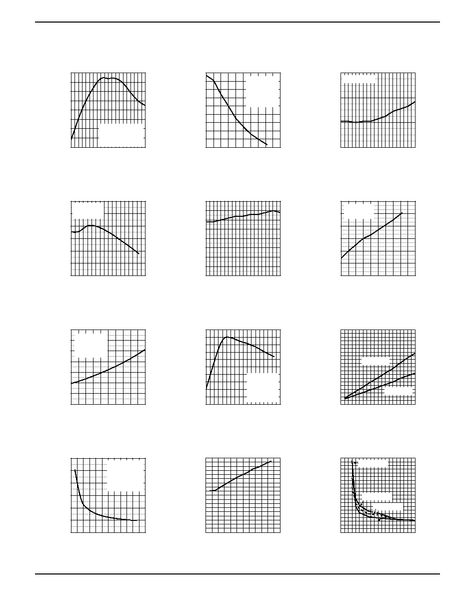
Typical Characteristics
-0.5
-0.4
-0.3
-0.2
-0
0.0
0.1
0.2
0.3
8
9 10 11 12 13 14 15 16 17 18
OSC FREQ. VARIATION (%)
V
CC
(V)
Oscillator Frequency
vs. V
CC
Voltage
F
OSC(NOM)
=200kHz
R
t
=9.47K
Ct=470pF
-2.5
-2
-1.5
-1
-0.5
0
0.5
1
1.5
2
-40
0
40
80
120
160
OSC FREQ. VARIATION (%)
TEMPERATURE (
∞
C)
Oscillator Frequency
vs. Temperature
V
CC
= 10V
R
BIAS
= 560K
R
t
= 9.47K
C
t
= 470pF
2.499
2.500
2.501
2.502
8
9 10 11 12 13 14 15 16 17 18
REFERENCE VOLTAGE (V)
V
CC
(V)
Error Amp Reference Voltage
vs. V
CC
Voltage
R
BIAS
= 560K
2.480
2.485
2.490
2.495
2.500
2.505
2.510
-40 -20 0 20 40 60 80 100120140
REFERENCE VOLTAGE (V)
TEMPERATURE (
∞
C)
Error Amp Reference Voltage
vs. Temperature
V
CC
= 10V
R
BIAS
= 560K
1.180
1.185
1.190
1.195
1.200
1.205
1.210
1.215
1.220
8
9 10 11 12 13 14 15 16 17 18
THRESHOLD (V)
V
CC
(V)
Line UVLO Threshold
vs. V
CC
1.18
1.19
1.2
1.21
1.22
1.23
1.24
-40
0
40
80
120
160
UVLO THRESHOLD (V)
TEMPERATURE (
∞
C)
Line UVLO Threshold
vs. Temperature
V
CC
=10V
R
BIAS
=560K
1.0
1.2
1.4
1.6
1.8
2.0
2.2
2.4
8
10
12
14
16
18
QUIESCENT CURRENT (mA)
V
CC
(V)
Quiescent Current
vs. V
CC
Voltage
R
BIAS
= 560K
R
t
= 9.47K
C
t
= 470pF
1.3
1.32
1.34
1.36
1.38
1.4
1.42
1.44
1.46
1.48
1.5
-40 -20 0 20 40 60 80 100120140
QUIESCENT CURRENT (mA)
TEMPERATURE (
∞
C)
Quiescent Current
vs. Temperature
V
CC
= 10V
R
BIAS
= 560K
R
t
= 9.47K
C
t
= 470pF
0
1
2
3
4
5
6
7
8
9
10
0
50
100
150
200
250
300
350
400
450
500
QUIESCENT CURRENT (mA)
GATE DRIVE FREQUENCY (kHz)
Quiescent Current
vs. Frequency
C
t
= 100pF
C
t
= 470pF
0.5
1
1.5
2
2.5
3
3.5
0
200 400 600 800 1000 1200
QUIESCENT CURRENT (mA)
R
BIAS
(k
)
Quiescent Current
vs. R
BIAS
V
CC
= 10V
R
t
= 9.53K
C
t
= 470pf
f
OSC
= 200kHz
0
10
20
30
40
50
60
70
80
90
0
200 400 600 800 1000 1200
DELAY (ns)
R
BIAS
(k
)
ISNS to Gate Output Delay
vs. R
BIAS
0
20
40
60
80
100
120
140
160
180
200
0
200
400
600
800
1000
1200
1400
1600
1800
2000
DELAY (ns)
OVERDRIVE (mV)
ISNS to Gate Output Delay
vs. Overdrive
R
BIAS
=160K
R
BIAS
=560K
R
BIAS
=360K