
Micrel Inc.
1849 Fortune Drive San Jose, Ca 95131
USA
tel + 1 (408) 944-0800
fax + 1 (408) 944-0970
http://www.micrel.com
MICRFKIT001-EU
Micrel AM Receiver Evaluation Kit
Advance Information
Introduction
Please read this document and the data sheets on the devices
Before use!
The kit is intended for evaluation purposes only; this may include test, experimentation
and verification of performance. It is not intended for incorporation into an end product.
This kit allows users to quickly evaluate the
performance of the Micrel MICRF001 QwikRadio
Receiver/Data
Demodulator in a typical application. The receiver IC together with
supporting circuitry is mounted on a compact single-in-line (SIL)
module with a pin out that is compatible with industry standard RF
receiver modules. The module plugs into the AM Receiver
Evaluation board which is fitted with a decoder that drives an LED
to indicate reception of a valid code.
The unique two pin MicroTx module is utilized in the matching
transmitter board. It drives either a short whip or a PCB loop that is
typical of aerials used in low power radio systems. A PIC based
encoder is used in the transmitter providing selectable modes of
operation including an `automatic transmit' mode that allows single
handed range testing. Data and circuitry are provided for all units.
Please check that the evaluation kit contains the following items:
Qnty
Description
1
Micrel MICRF001 Receiver module
1
AM Receiver Evaluation board
1
Micro TX Evaluation board
2
9V Alkaline PP3 Battery
1
Thin black 160mm 3/4 wave whip Antenna with rubber tip (Receiver)
1
Thin black 110mm whip Antenna with rubber tip (Transmitter)
1
Micrel MICRF001 QwikRadio Handbook
This kit operates on 433MHZ

MICRFKIT001-EU
December 1998
2
Micrel
Micrel
Operation and Use
The primary function of this kit is to demonstrate the physical distance (range) over which reliable communications can
be obtained from the Micrel MICRF001 receiver IC when used in combination with a SAW based transmitter operating
at the typical power levels allowed by the applicable authorities.
The performance of any radio system cannot accurately be predicted or guaranteed, laboratory figures can be
misleading and it is only by real world testing that confidence can be achieved. The `range test' provides the user with a
practical `feel' for the reliability and performance of a radio link in their applications environment.
It is strongly recommended that users assess the performance of these units in the intended environment of use. While
it is possible to obtain typical ranges of about 75 meters with the PCB loop aerial and over 100 meters with the whip
aerial, these ranges will be modified by the local conditions. In open ground with aerials one meter above ground better
ranges can be obtained than from room to room, through partitions or walls, inside an office or a factory. Additionally,
users can note how the aerial type or position and its proximity to large metallic objects affect range. The effect of
interference sources such as other radio devices (intentional radiators) or for example, local microprocessor clocks
(unintentional radiators) can also be assessed.
Micrel MICRF2000B Receiver Module
This board incorporates the Micrel MICRF001 QwikRadio
Receiver/Data
Demodulator in an industry standard pin out module that allows users to test
and evaluate the device in new or existing applications.
In general the MICRF2000B Module will plug directly into "industry standard"
receiver sockets. Pin numbering schemes vary with manufacturer. Pin positions
shown blank have no pin fitted.
Pin Pitch is 0.1".
The three Vcc pins of the MicrelRx are internally connected and the RF Gnd and the Gnd pins should be externally
connected to a substantial 0V ground plane on the motherboard. This provides a 'ground reference' for the aerial.
MICRFKIT001-EU
December 1998
3
Micrel
Micrel
AM Receiver Evaluation Board
This board `clips' on the top of 9V PP3 battery. A slide on/off switch connects the
battery via reverse protection diode to a 78L05 5V 100mA regulator that provides
power to the receiver module and the Holtek TM HT12D decoder IC. A � wave whip
aerial (160mm) plugs into the board via a 0.1" Molex connector.
Clock frequency of the decoder IC is set by resistor R1 and is set to match the
transmitter data rate. (See Appendix A) The module digital data output drives the DIN
of the decoder whose `address' is set by PCB solder `blobs' on the underside of the
board. The default factory set code address is A0,A2,A4,A6 low and A1,A3,A5,A7
high. This produces an alternating 1-0 bit pattern.
The `valid code' LED lights on an address match only. The data bit outputs are neither
used nor connected
System Operation
Carefully plug the receiver module into the turned pin sockets on the board. Plug the 160mm supplied whip aerial in to
the Molex socket. (A blanking pin is fitted into the RF ground pin) Clip the board to a PP3 9V battery and switch on.
When a valid code is being received the LED will light. (See Range Testing) Please note: The receiver module takes
some time to `charge-up" as the AGC capacitor charges to its operational voltage.
Transmitter Operation
This board `clips' on the top of 9V PP3 battery. A slide on/off switch connects the battery via reverse protection diode D2
to a regulator that provides power to the board. A programmed PIC12C508 is used to `key' the SAW (Surface Acoustic
Wave) based transmitter module On or Off via the RF power setting resistor R2. The RF output of the transmitter
module can be connected to a tuned PCB loop aerial or a tuned short whip aerial by the jumper link CN1. Both these
aerials are pre-aligned at the factory for maximum RF output and users should have the means to measure RF field
strength before adjusting the tuning.
The PIC12C508 is programmed with code that emulates the HoltekTM HT12E data format and the address and data are
both programmed in ROM to match the receiver decoder and cannot be altered by the user.
Single Shot Mode
When the transmitter push button is momentarily pressed the PIC generates a serial output word that drives the
transmitter module This comprises an eight-bit address and four bits of (dummy) data which is repeated twenty times
before shutting down. An LED lights for the duration of the RF transmission.
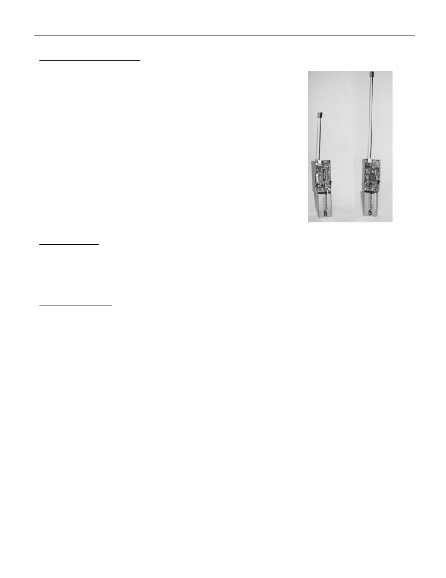
Tx Board (left) Rx Board (Right)

MICRFKIT001-EU
December 1998
4
Micrel
Micrel
Automatic Mode
If the push button is held pressed for more than four seconds the transmitter will go into an `automatic repeat' mode after
which the button can be released. In this mode the transmitter will continuously send a transmission at one-second
intervals allowing single-handed range testing. Escape from this mode by switching the power off.
Carrier Wave Mode
A third mode of operation is obtained by holding the push button pressed for more than eight seconds. The keyed on off
data modulation is terminated and the transmitter is switched to CW (Carrier Wave) operation. This mode is used for
tuning the aerials. Escape from this mode by switching the power off.
Range Testing
1.
Check that the transmitter and receiver are operating correctly at close distance.
2.
Find a large clear open air space that has no obstructions such as a park or field. Ensure that there are no power
lines, radio transmitters (cellular, broadcast, taxi, and radar) or other local sources of interference.
3.
Check that the operating frequency is clear of interference with a hobby type `scanner' type receiver.
4.
Set the transmitter to `Auto' mode and place on a non-metallic surface about one meter above ground. A wooden
chair or table is ideal.
5.
Hold the receiver at waist height with the aerial held vertically and well away from your body, observe the regular
`Valid Code' signal being received and indicated by the LED.
6.
Slowly walk away until reception becomes intermittent. Reorient the aerial and note how the proximity of your body
to the aerial affects reception.
7.
When no more range can be achieved, switch off, pace out and note the distance back to the transmitter. This
provides a useful reference.
8.
Change the type of transmitter aerial used; e.g. whip to loop and repeat above.
9.
Now perform a similar test within a building. An electrically quiet environment such as an office should be used
initially. The effect of walls, doors, windows and large metallic surfaces such as filing cabinets should be observed.
At the limits of range note how moving even a very short distance (2-3") causes the signal to `fade out'. This is due
to reflections that may add or subtract from the direct signal.
10. Place the transmitter inside a metal filing cabinet and close it. Be surprised by the result! Short wavelength UHF
signals `leak' out of the thin slots between the drawers and the body of the cabinet. Mentally note that what gets out
can also get in and that the `screening can' you were going to use on the receiver to `keep out interference' needs to
be almost airtight to work at all!
11. After this exercise place the receiver beside your favorite 300MHZ PC microprocessor board and take the
transmitter for a short walk. Does it work better with the processor running or when it is switched off? Why? Will the
screening can help? Might there be a better location for the aerial?
12. Shorten the receiver aerial or wind it around a metal case or place it alongside a large circuit board. What effect
does this have on range? Generally you may note it does not improve it!
The above effects are due mainly to the aerial and its position. While every effort has been made by us to provide
the best performance from the modules, it is up to the user to provide an efficient aerial system at both ends of
the link. Aerials like to be in "free space" and it is often said that the space around the aerial is as important as the
aerial itself. A short piece of wire (of the correct length and in the right place) will work just as well as any fancy
custom built `rubber duck' aerial. An aid to aerial efficiency is a `ground plane'. This provides something for the
aerial to work against. Just as a wooden ruler will `ping' pleasingly when clamped to the edge of a desk and not
when held between finger and thumb, the same applies (in general) to aerials.
A little research, testing and application of the acquired knowledge will reap the reward of a radio link that works
consistently well despite the considerations above.
MICRFKIT001-EU
December 1998
5
Micrel
Micrel
Product Order Codes
Description
Order Code
Complete Kit as below incl. Box, etc
MICRFKIT001EU-433
Micrel MICRF001 Receiver Module (433MHZ)
MICRF2000B
Other Frequencies
The receiver module can be configured during manufacture to operate on any frequency between 300 and 440 MHZ.
The transmitter module however is based on SAW (Surface Acoustic Wave) resonators, which are only available on
limited frequencies. A 418MHZ version is available for UK customers. Please contact the Sales Office for other
variations.
Document History
Issue
Date
Revision
1.0
Oct-98
Preliminary
Limitation of Use
The kit is intended for evaluation purposes only; this may include test, experimentation and verification of performance. It
not intended for incorporation into an end product.
Design
The kit was designed and is manufactured by Low Power Radio Solutions (LPRS), a division of The Quantelec Group
Ltd. for Micrel Inc. It is designed to comply with all relevant UK & EU Radio & EMC Standards.
Low Power Radio Solutions (The Quantelec Group Ltd) is an approved RF Design Partner to Micrel Inc for QwikRadioTM
products.
Warranty
The kit is guaranteed for a period of thirty days from date of purchase against manufacturing or component defects.
Disclaimer
The Quantelec Group Ltd and Micrel, Inc. both have an ongoing policy to improve the performance and reliability of their
products; we therefore reserve the right to make changes without notice. The information contained in this data sheet is
believed to be accurate. We do not, however, assume any responsibility for errors nor any liability arising from the
application or use of any product or circuit described herein. This data sheet neither states nor implies warranty of any
kind, including fitness for any particular application.
Radio can be subject to both unintentional and intentional interference and no guarantees are provided for the exclusive
use of the low power radio bands by the regulatory authorities. Some bands in some parts of the world may also be
shared with high power users. Radio should be thought of as a `statistical communication' medium and these limitations
(of radio in general) should be carefully considered before incorporating radio technology into a product particularly if
there may be any safety implications.