DESCRIPTION
FEATURES
JK FLIP-FLOP
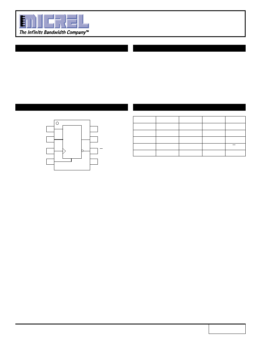
PIN CONFIGURATION/BLOCK DIAGRAM
J
K
R
CLK
Qn+1
L
L
L
Z
Qn
L
H
L
Z
L
H
L
L
Z
H
H
H
L
Z
Qn
X
X
H
X
L
NOTE:
1. Z = LOW-to-HIGH transition.
SOIC
TOP VIEW
1
2
3
4
5
6
7
8
J
V
CC
Q
V
EE
K
R
Q
R
CLK
J
K
Rev.: E
Amendment: /0
Issue Date:
August, 1998
SY10EL35
SY100EL35
TRUTH TABLE
(1)
s
525ps propagation delay
s
2.2GHz toggle frequency
s
High bandwidth output transistions
s
Internal 75K
input pull-down resistors
s
Available in 8-pin SOIC package
The SY10/100EL35 are high-speed JK Flip-Flops. The
J/K data enters the master portion of the flip-flop when
the clock is LOW and is transferred to the slave and,
thus, the outputs, upon a positive transition of the clock.
The reset pin is asynchronous and is activated with a
logic HIGH.
1

4
SY10EL35
SY100EL35
Micrel
MICREL-SYNERGY
3250 SCOTT BOULEVARD
SANTA CLARA
CA 95054
USA
TEL
+ 1 (408) 980-9191
FAX
+ 1 (408) 914-7878
WEB
http://www.micrel.com
This information is believed to be accurate and reliable, however no responsibility is assumed by Micrel for its use nor for any infringement of patents or
other rights of third parties resulting from its use. No license is granted by implication or otherwise under any patent or patent right of Micrel Inc.
© 2000 Micrel Incorporated