DESCRIPTION
FEATURES
JK FLIP-FLOP
PIN CONFIGURATION/BLOCK DIAGRAM
J
K
R
CLK
Qn+1
L
L
L
Z
Qn
L
H
L
Z
L
H
L
L
Z
H
H
H
L
Z
Qn
X
X
H
X
L
NOTE:
1. Z = LOW-to-HIGH transition.
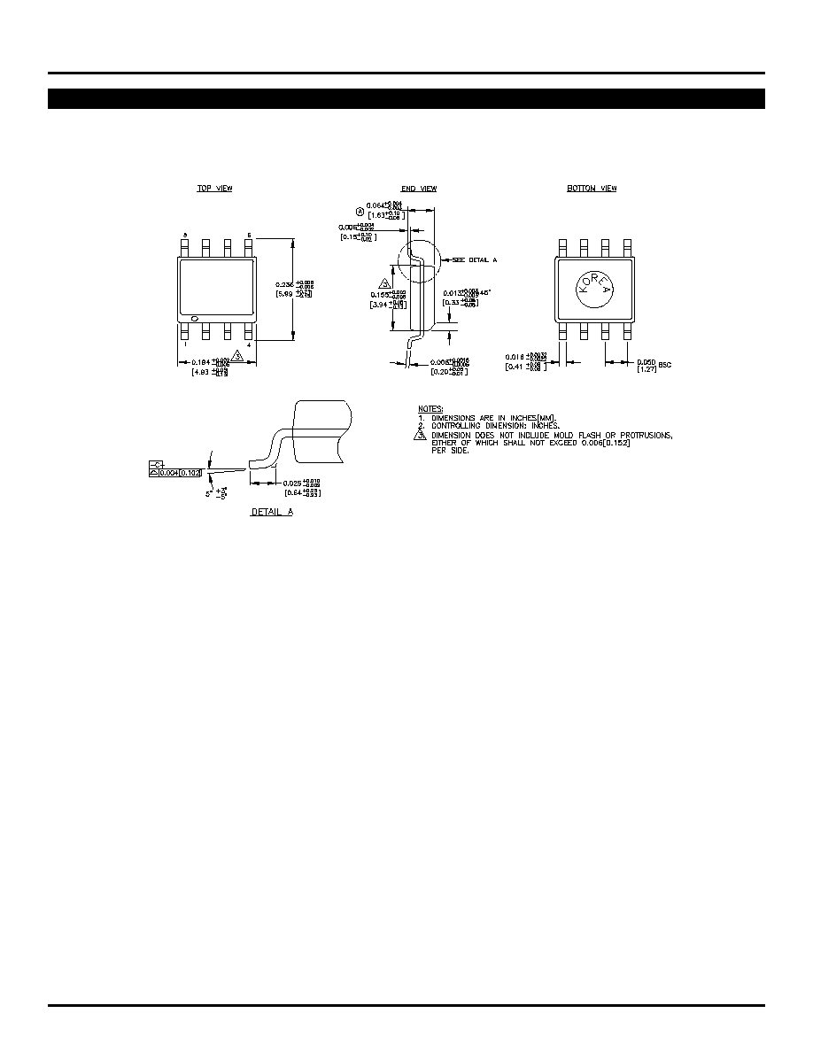
SOIC
TOP VIEW
1
2
3
4
5
6
7
8
J
V
CC
Q
V
EE
K
R
Q
R
CLK
J
K
SY10EL35
SY100EL35
FINAL
TRUTH TABLE
(1)
s
525ps propagation delay
s
2.2GHz toggle frequency
s
High bandwidth output transistions
s
Internal 75K
input pull-down resistors
s
Available in 8-pin SOIC package
The SY10/100EL35 are high-speed JK Flip-Flops. The
J/K data enters the master portion of the flip-flop when
the clock is LOW and is transferred to the slave and,
thus, the outputs, upon a positive transition of the clock.
The reset pin is asynchronous and is activated with a
logic HIGH.
1
Rev.: F
Amendment: /0
Issue Date:
February 2003

2
SY10EL35
SY100EL35
Micrel
T
A =
≠40
∞
C
T
A =
0
∞
C
T
A =
+25
∞
C
T
A =
+85
∞
C
Symbol
Parameter
Min.
Typ.
Max.
Min.
Typ.
Max.
Min.
Typ.
Max.
Min.
Typ.
Max.
Unit
f
MAX
Maximum Toggle
1.4
2.0
--
1.8
2.2
--
1.8
2.2
--
1.8
2.2
--
GHz
Frequency
t
PLH
Propagation Delay
CLK
290
515
--
340
515
690
350
525
700
395
570
745
ps
t
PHL
to Output
MR
225
450
--
275
450
625
275
450
625
350
525
700
t
S
Set-up Time
150
0
--
150
0
--
150
0
--
150
0
--
ps
t
H
Hold Time
250
100
--
250
100
--
250
100
--
250
100
--
ps
t
RR
Reset Recovery
400
200
--
400
200
--
400
200
--
400
200
--
ps
t
PW
Minimum Pulse Width
400
--
--
400
--
--
400
--
--
400
--
--
ps
CLK, Reset
t
r
Output Rise/Fall Times Q
100
225
350
100
225
350
100
225
350
100
225
350
ps
t
f
(20% to 80%)
AC ELECTRICAL CHARACTERISTICS
V
EE
= V
EE
(Min.) to V
EE
(Max.); V
CC
= GND
PRODUCT ORDERING CODE
DC ELECTRICAL CHARACTERISTICS
T
A =
≠40
∞
C
T
A =
0
∞
C
T
A =
+25
∞
C
T
A =
+85
∞
C
Symbol
Parameter
Min.
Typ.
Max.
Min.
Typ.
Max.
Min.
Typ.
Max.
Min.
Typ.
Max.
Unit
I
EE
Power Supply Current
mA
10EL
--
27
32
--
27
32
--
27
32
--
27
32
100EL
--
27
32
--
27
32
--
27
32
--
32
37
V
EE
Power Supply Voltage
V
10EL
--
≠5.2
--
≠4.75
≠5.2
≠5.5
≠4.75
≠5.2
≠5.5
≠4.75
≠5.2
≠5.5
100EL
--
≠4.5
--
≠4.20
≠4.5
≠5.5
≠4.20
≠4.5
≠5.5
≠4.20
≠4.5
≠5.5
I
IH
Input HIGH Current
--
--
150
--
--
150
--
--
150
--
--
150
µ
A
V
EE
= V
EE
(Min.) to V
EE
(Max.); V
CC
= GND
Ordering
Package
Operating
Marking
Code
Type
Range
Code
SY10EL35ZC
Z8-1
Commercial
HEL35
SY10EL35ZCTR*
Z8-1
Commercial
HEL35
SY100EL35ZC
Z8-1
Commercial
XEL35
SY100EL35ZCTR*
Z8-1
Commercial
XEL35
*Tape and Reel
Note 1.
Recommended for new designs.
Ordering
Package
Operating
Marking
Code
Type
Range
Code
SY10EL35ZI
(1)
Z8-1
Industrial
HEL35
SY10EL35ZITR*
(1)
Z8-1
Industrial
HEL35
SY100EL35ZI
(1)
Z8-1
Industrial
XEL35
SY100EL35ZITR*
(1)
Z8-1
Industrial
XEL35
*Tape and Reel

4
SY10EL35
SY100EL35
Micrel
MICREL, INC.
1849 FORTUNE DRIVE
SAN JOSE, CA 95131
USA
TEL
+ 1 (408) 944-0800
FAX
+ 1 (408) 944-0970
WEB
http://www.micrel.com
The information furnished by Micrel in this datasheet is believed to be accurate and reliable. However, no responsibility is assumed by Micrel for its use.
Micrel reserves the right to change circuitry and specifications at any time without notification to the customer.
Micrel Products are not designed or authorized for use as components in life support appliances, devices or systems where malfunction of a product can
reasonably be expected to result in personal injury. Life support devices or systems are devices or systems that (a) are intended for surgical implant into
the body or (b) support or sustain life, and whose failure to perform can be reasonably expected to result in a significant injury to the user. A Purchaser's
use or sale of Micrel Products for use in life support appliances, devices or systems is at Purchaser's own risk and Purchaser agrees to fully indemnify
Micrel for any damages resulting from such use or sale.
© 2003 Micrel, Incorporated.