Pin
Function
D
0
≠D
5
Preset Data Inputs
Q
0
≠Q
5
Differential Data Outputs
S
1
, S
2
Mode Control Pins
MR
Master Reset
CLK
Clock Input
C
OUT
, C
OUT
Carry Out Output (Active LOW)
CL
OUT
Look-Ahead-Carry Output
C
IN
Carry-In Input (Active LOW)
CL
IN
Look-Ahead-Carry Input
V
CCO
V
CC
to Output
DESCRIPTION
FEATURES
s
550MHz count frequency
s
Extended 100E V
EE
range of ≠4.2V to ≠5.5V
s
Look-ahead-carry input and output
s
Fully synchronous up and down counting
s
Asynchronous Master Reset
s
Internal 75K
input pull-down resistors
s
Available in 28-pin PLCC package
The SY10/100E136 are 6-bit synchronous, presettable,
cascadable universal counters. These devices generate
a look-ahead-carry output and accept a look-ahead-carry
input. These two features allow for the cascading of
multiple E136s for wider bit width counters that operate
at very nearly the same frequency as the stand-alone
counter.
The CL
OUT
output will pulse LOW for one clock cycle
one count before the E136 reaches terminal count. The
C
OUT
output will pulse LOW for one clock cycle when
the counter reaches terminal count. For more information
on utilizing the look-ahead-carry features of the device,
please refer to the applications section of this data sheet.
The differential C
OUT
output facilitates the E136's use in
programmable divider and self-stopping counter
applications.
Unlike the H136 and other similar universal counter
designs, the E136 carry-out and look-ahead-carry-out
signals are registered on chip. This design alleviates the
glitch problem seen on many counters where the carry-
out signals are merely gated. Because of this architecture,
there are some minor functional differences between the
E136 and H136 counters. The user, regardless of
familiarity with the H136, should read this data sheet
carefully. Note specifically (see block diagram) the
operation of the carry-out outputs and the look-ahead-
carry-in input when utilizing the Master Reset.
When left open, all of the input pins will be pulled
LOW via an input pulldown resistor. The Master Reset is
an asynchronous signal which, when asserted, will force
the Q outputs LOW.
The Q outputs need not be terminated for the E136 to
function properly. In fact, if these outputs will not be
used in a system, it is recommended that they be left
open to save power and minimize noise. This practice
will minimize switching noise which can reduce the
maximum count frequency of the device, or significantly
reduce margins against other noise in the system.
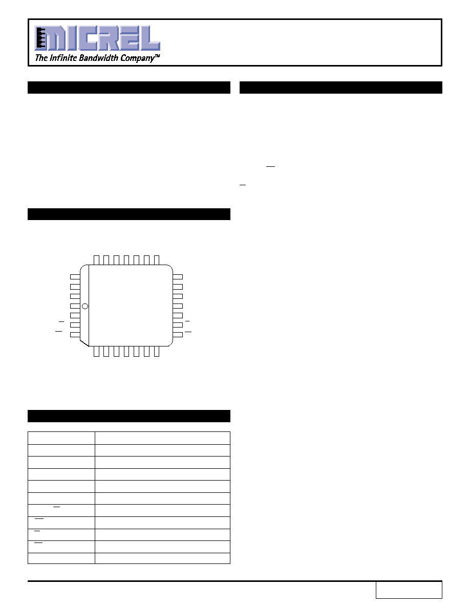
PIN CONFIGURATION
PIN NAMES
SY10E136
SY100E136
FINAL
6-BIT UNIVERSAL
UP/DOWN COUNTER
Rev.: C
Amendment: /1
Issue Date: February, 1998
D
4
V
EE
D
2
S
2
C
IN
CLK
Q
4
26
27
28
1
2
3
4
18
17
16
15
14
13
12
25
24
23
22
21
20
19
5
6
7
8
9
10
11
CL
IN
S
1
V
CCO
Q
1
Q
3
Q
5
PLCC
TOP VIEW
J28-1
D
3
V
CCO
D
5
Q
2
V
CC
V
CCO
C
OUT
C
OUT
CL
OUT
Q
0
V
CCO
D
0
D
1
MR
V
CCO
1
2
SY10E136
SY100E136
Micrel
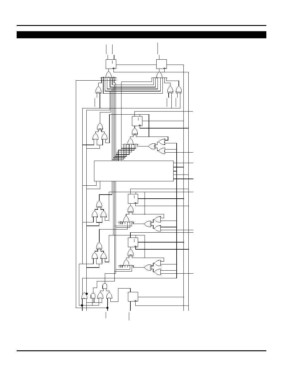
LOGIC DIAGRAM
BLOCK DIAGRAM
(1)
NOTE:
1. This diagram is provided for understanding of logic operation only. It should not be used for propagation delays as many gate functions are achieved
internally without incurring a full gate delay.
E136 Universal Up/Down Counter Logic Diagram
Q
D
S
C
OUT
C
OUT
CL
OUT
Q
D
S
Q
QM1
QM0
QM0
Q
D
R
Q
BITS 2 ≠ 4
Q
D
R
Q
Q
D
R
Q
Q
D
S
S1
S2
C
IN
CL
IN
MR
CLK
D
0
Q
0
D
1
Q
1
D
2
≠
D
4
Q
2
≠
Q
5
D
5
Q
5
3
SY10E136
SY100E136
Micrel
LOGIC DIAGRAM
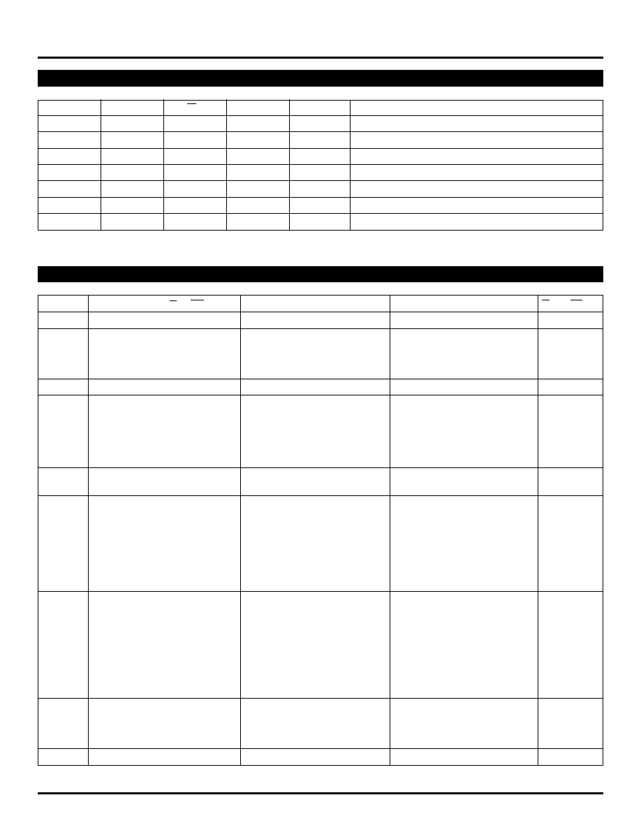
TRUTH TABLE
(1)
S
1
S
2
C
IN
MR
CLK
Function
L
L
X
L
Z
Preset Parallel Data Inputs
L
H
L
L
Z
Increment (Count Up)
L
H
H
L
Z
Hold Count
H
L
L
L
Z
Decrement (Count Down)
H
L
H
L
Z
Hold Count
H
H
X
L
Z
Hold Count
X
X
X
H
X
Reset (Qn = LOW; C
OUT
= HIGH)
NOTE:
1. Expanded truth table included on following pages.
LOGIC DIAGRAM
EXPANDED TRUTH TABLE
(1)
Function
S
1
S
2
MR
C
IN
CL
IN
CLK
D
5
D
4
D
3
D
2
D
1
D
0
Q
5
Q
4
Q3
Q
2
Q
1
Q
0
C
OUT
CL
OUT
Preset
L
L
L
X
X
Z
L
L
L
L
H
H
L
L
L
L
H
H
H
H
Down
H
L
L
L
L
Z
X
X
X
X
X
X
L
L
L
L
H
L
H
H
H
L
L
L
L
Z
X
X
X
X
X
X
L
L
L
L
L
H
H
L
H
L
L
L
L
Z
X
X
X
X
X
X
L
L
L
L
L
L
L
H
H
L
L
L
L
Z
X
X
X
X
X
X
H
H
H
H
H
H
H
H
Preset
L
L
L
X
X
Z
H
H
H
H
L
L
H
H
H
H
L
L
H
H
Up
L
H
L
L
L
Z
X
X
X
X
X
X
H
H
H
H
L
H
H
H
L
H
L
L
L
Z
X
X
X
X
X
X
H
H
H
H
H
L
H
L
L
H
L
L
L
Z
X
X
X
X
X
X
H
H
H
H
H
H
L
H
L
H
L
L
L
Z
X
X
X
X
X
X
L
L
L
L
L
L
H
H
L
H
L
L
L
Z
X
X
X
X
X
X
L
L
L
L
L
H
H
H
L
H
L
L
L
Z
X
X
X
X
X
X
L
L
L
L
H
L
H
H
Hold
H
H
L
X
X
Z
X
X
X
X
X
X
L
L
L
L
H
L
H
H
H
H
L
X
X
Z
X
X
X
X
X
X
L
L
L
L
H
L
H
H
Down
H
L
L
L
L
Z
X
X
X
X
X
X
L
L
L
L
L
H
H
L
Hold
H
L
L
H
L
Z
X
X
X
X
X
X
L
L
L
L
L
H
H
H
Down
H
L
L
L
L
Z
X
X
X
X
X
X
L
L
L
L
L
L
L
H
Hold
H
L
L
H
L
Z
X
X
X
X
X
X
L
L
L
L
L
L
H
H
H
L
L
H
L
Z
X
X
X
X
X
X
L
L
L
L
L
L
H
H
H
L
L
H
H
Z
X
X
X
X
X
X
L
L
L
L
L
L
H
H
Hold
H
L
L
L
H
Z
X
X
X
X
X
X
L
L
L
L
L
L
L
H
H
L
L
L
L
Z
X
X
X
X
X
X
L
L
L
L
L
L
L
H
Hold
H
H
L
L
L
Z
X
X
X
X
X
X
L
L
L
L
L
L
L
H
Preset
L
L
L
X
X
Z
H
H
H
H
L
L
H
H
H
H
L
L
H
H
Up
L
H
L
L
L
Z
X
X
X
X
X
X
H
H
H
H
L
H
H
H
L
H
L
L
L
Z
X
X
X
X
X
X
H
H
H
H
H
L
H
L
Hold
L
H
L
H
L
Z
X
X
X
X
X
X
H
H
H
H
H
L
H
H
Up
L
H
L
L
L
Z
X
X
X
X
X
X
H
H
H
H
H
H
L
H
Hold
L
H
L
H
L
Z
X
X
X
X
X
X
H
H
H
H
H
H
H
H
L
H
L
H
H
Z
X
X
X
X
X
X
H
H
H
H
H
H
H
H
Hold
L
H
L
L
L
Z
X
X
X
X
X
X
H
H
H
H
H
H
L
H
Up
L
H
L
L
L
Z
X
X
X
X
X
X
L
L
L
L
L
L
H
H
L
H
L
L
L
Z
X
X
X
X
X
X
L
L
L
L
L
H
H
H
L
H
L
L
L
Z
X
X
X
X
X
X
L
L
L
L
H
L
H
H
L
H
L
L
L
Z
X
X
X
X
X
X
L
L
L
L
H
H
H
H
Reset
X
X
H
X
X
X
X
X
X
X
X
X
L
L
L
L
L
L
H
H
NOTE:
1. Z = LOW-to-HIGH transition
4
SY10E136
SY100E136
Micrel
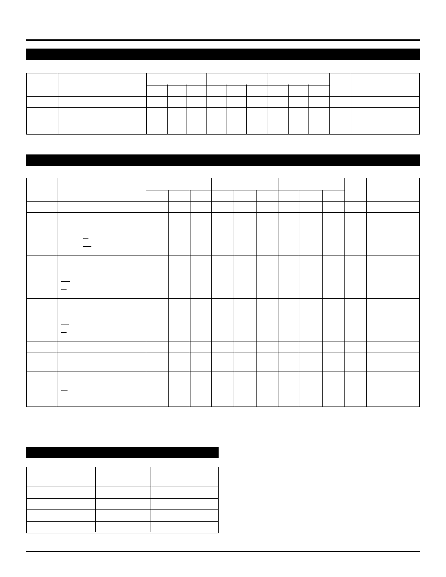
PRODUCT ORDERING CODE
Ordering
Package
Operating
Code
Type
Range
SY10E136JC
J28-1
Commercial
SY10E136JCTR
J28-1
Commercial
SY100E136JC
J28-1
Commercial
SY100E136JCTR
J28-1
Commercial
T
A
= 0
∞
C
T
A
= +25
∞
C
T
A
= +85
∞
C
Symbol
Parameter
Min.
Typ.
Max.
Min.
Typ.
Max.
Min.
Typ.
Max.
Unit
Condition
f
COUNT
Maximum Count Frequency
550
650
--
550
650
--
550
650
--
MHz
--
t
PLH
Propagation Delay to Output
ps
--
t
PHL
CLK to Q
850
1150
1450
850
1150
1450
850
1150
1450
MR to Q
850
1150
1450
850
1150
1450
850
1150
1450
CLK to C
OUT
800
1150
1300
800
1150
1300
800
1150
1300
CLK to CL
OUT
825
1150
1400
825
1150
1400
825
1150
1400
t
S
Set-up Time
ps
--
S
1
, S
2
1500
650
--
1500
650
--
1500
650
--
D
800
400
--
800
400
--
800
400
--
CL
IN
150
0
--
150
0
--
150
0
--
C
IN
800
400
--
800
400
--
800
400
--
t
H
Hold Time
ps
--
S
1
, S
2
150
≠200
--
150
≠200
--
150
≠200
--
D
150
≠250
--
150
≠250
--
150
≠250
--
CL
IN
300
0
--
300
0
--
300
0
--
C
IN
150
≠250
--
150
≠250
--
150
≠250
--
t
RR
Reset Recovery Time
1000
700
--
1000
700
--
1000
700
--
ps
--
t
PW
Minimum Pulse Width
700
400
--
700
400
--
700
400
--
ps
--
CLK, MR
t
r
Rise/Fall Times
ps
--
t
f
20% to 80%
C
OUT
275
--
600
275
--
600
275
--
600
Other
300
--
700
300
--
700
300
--
700
LOGIC DIAGRAM
DC ELECTRICAL CHARACTERISTICS
V
EE
= V
EE
(Min.) to V
EE
(Max.); V
CC
= V
CCO
= GND
T
A
= 0
∞
C
T
A
= +25
∞
C
T
A
= +85
∞
C
Symbol
Parameter
Min.
Typ. Max. Min.
Typ.
Max. Min.
Typ.
Max.
Unit
Condition
I
IH
Input HIGH Current
--
--
150
--
--
150
--
--
150
µ
A
--
I
EE
Power Supply Current
mA
--
10E
--
125
150
--
125
150
--
125
150
100E
--
125
150
--
125
150
--
140
170
LOGIC DIAGRAM
AC ELECTRICAL CHARACTERISTICS
V
EE
= V
EE
(Min.) to V
EE
(Max.); V
CC
= V
CCO
= GND
5
SY10E136
SY100E136
Micrel
LOGIC DIAGRAM
APPLICATIONS INFORMATION
Overview
The SY10E/100E136 are 6-bit synchronous, presettable,
cascadable universal counters. Using the S
1
and S
2
control
pins, the user can select between preset, count up, count
down and hold count. The Master Reset pin will reset the
internal counter and set the C
OUT
, CL
OUT
and CL
IN
flip-
flops. Unlike previous 136-type counters, the carry-out
outputs will go to a high state during the preset operation.
In addition, since the carry-out outputs are registered, they
will not go low if terminal count is loaded into the register.
The look-ahead-carry-out output functions similarly.
Note from the schematic the use of the master information
from the least significant bits for control of the two carry-out
functions. This architecture not only reduces the carry-out
delay, but is essential to incorporate the registered carry-
out functions. In addition to being faster, the resulting carry-
out signals are stable and glitch free because these functions
are registered.
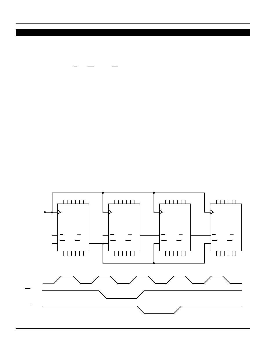
Cascading Multiple E136 Devices
Many applications require counters significantly larger than
the 6 bits available with the E136. For these applications,
several E136 devices can be cascaded to increase the bit
width of the counter to meet the needs of the application.
In the past, cascading several 136-type universal counters
necessarily impacted the maximum count frequency of the
resulting counter chain. This performance impact was the
result of the terminal count signal of the lower order counters
Figure 1. 24-bit Cascaded E136 Counter
having to ripple through the entire counter chain. As a
result, past counters of this type were not widely used in
large bit counter applications.
An alternative counter architecture similar to the E016
binary counter was implemented to alleviate the need to
ripple propagate the terminal count signal. Unfortunately,
these types of counters require external gating for cascading
designs of more than two devices. In addition to requiring
additional components, these external gates limit the
cascaded count frequency to a value less than the free
running count frequency of a single counter. Although there
is a performance impact with this type of architecture, it is
minor compared to the impact of the ripple propagate
designs. As a result, the E016-type counters have been
used extensively in applications requiring very high speed,
wide bit width synchronous counters.
Several improvements have been incorporated to past
universal counter designs in the E136 universal counter.
These enhancements make the E136 the unparalleled leader
in its class. With the addition of look-ahead-carry features
on the terminal count signal, very large counter chains can
be designed which function at very nearly the same clock
frequency as a single free running device. More importantly,
these counter chains require no external gating. Figure 1
below illustrates the interconnect scheme for using the look-
ahead-carry features of the E136 counter.
CLK
C
IN
CL
IN
CLOCK
"LO"
"LO"
C
OUT
LSB
Q
0
≠ Q
5
"LO"
MSB
CLK
C
OUT
CL
OUT
111101
111110
111111
Q
0
≠ Q
5
Q
0
≠ Q
5
Q
0
≠ Q
5
CL
OUT
D
0
≠ D
5
D
0
≠ D
5
D
0
≠ D
5
D
0
≠ D
5
C
IN
CL
IN
C
OUT
CL
OUT
C
IN
CL
IN
C
OUT
CL
OUT
C
IN
CL
IN
C
OUT
CL
OUT
CLK
CLK
CLK
000001
000000