 | –≠–ª–µ–∫—Ç—Ä–æ–Ω–Ω—ã–π –∫–æ–º–ø–æ–Ω–µ–Ω—Ç: ML6633IS | –°–∫–∞—á–∞—Ç—å:  PDF PDF  ZIP ZIP |
September 1998
ML6633
*
High Speed Fiber Optic LED Driver
GENERAL DESCRIPTION
The ML6633 is a high speed fiber optic LED driver suited
for networking applications up to 200 Mbps. The part is
capable of driving up to 82mA of current through a fiber
optic LED from an ECL level input signal. Its efficient
output stage provides a high current that can be
programmed for accurate absolute output level which
insures precise launch power.
The LED driver's output stage provides a fast well
matched rise and fall time through a unique differential
output stage.
The ML6633 high speed fiber optic LED driver is
implemented in BiCMOS process and is available in an
8-pin SOIC package.
FEATURES
n Data rates up to 200Mbps
n Current driven output for accurate launch power
n Programmable output current from 20mA to 82mA
n High Efficiency Output Stage
n Low EMI/RFI Noise
n ECL inputs
n Industrial temperature version available
n May be used with ML6622 quantizer
APPLICATIONS
n FDDI
n Fast Ethernet, 100BASE-FX
n ATM (SONET), 155Mbps
n Proprietary high-speed fiber optic data links
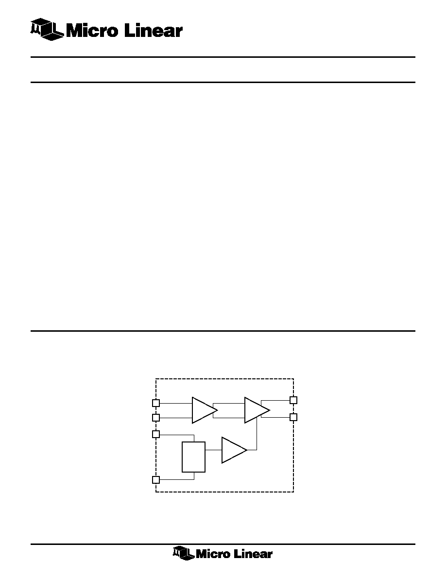
BLOCK DIAGRAM
*Some Packages Are Obsolete
1
+
BUFFER
≠
+
DRIVER
≠
IOUT
REF
RTSET
ECLP
ECLN
V
CC
GND
6
5
8
3
2
7
2
ML6633
PIN
NAME
DESCRIPTION
1
NC
No Connect
2
ECLP
Positive ECL data input controls signal
to the LED
3
ECLN
Negative ECL data input
4
NC
No Connect
5
GND
Negative power supply ground
PIN
NAME
DESCRIPTION
6
RTSET
Output current programming pin.
Connect a resistor of value 2/I
LED
from
this pin to ground to set the high LED
output current
7
IOUT
Fiber optic LED drive pin. Connect the
LED between this pin and V
CC
8
V
CC
5V power supply
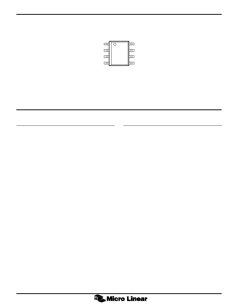
PIN CONNECTION
PIN DESCRIPTION
ML6633
8-Pin SOIC (S08)
1
2
3
4
8
7
6
5
NC
ECLP
ECLN
NC
VCC
IOUT
RTSET
GND
TOP VIEW
3
ML6633
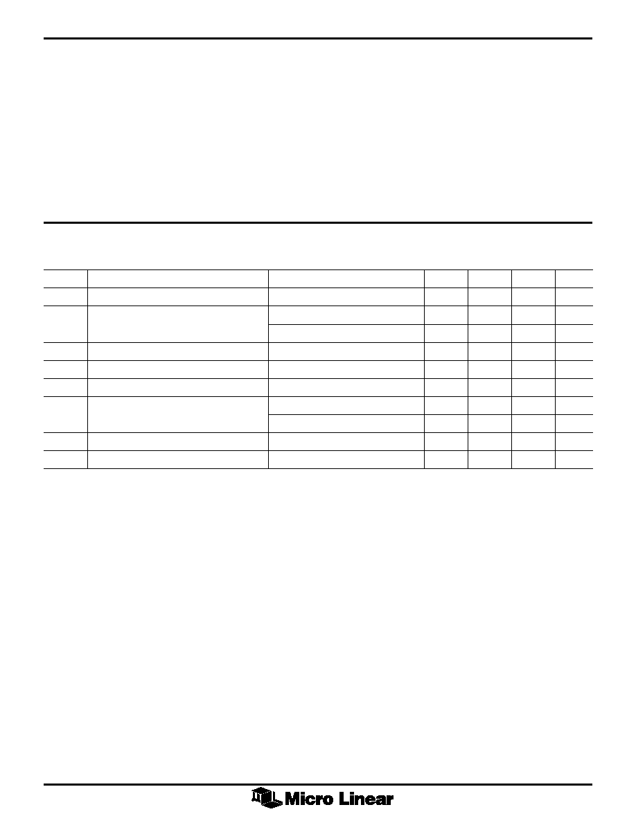
ELECTRICAL CHARACTERISTICS
Unless otherwise specified, V
CC
= 5V ± 5%, RTSET = 26.1
± 1%, T
A
= Operating Temperature Range, (Note 1)
SYMBOL
PARAMETER
CONDITIONS
MIN
TYP
MAX
UNITS
I
CC
Supply Current
40+I
OUT
mA
I
LEDH
LED Current Accuracy (IOUT) High
C Suffix
70
75
82
mA
I Suffix
65
75
82
mA
I
LEDL
Low
0.1
mA
t
R
Rise Time (IOUT)
2
ns
t
F
Fall Time (IOUT)
2
ns
t
PLH
Propagation Delay (IOUT)
Low to High
10
ns
t
PHL
High to Low
10
ns
t
PWD
Pulse Width Distortion (IOUT)
0.5
ns
I
ECL
ECL Input Current
20
µA
Note 1:
Limits are guaranteed by 100% testing, sampling, or correlation with worst-case test conditions.
ABSOLUTE MAXIMUM RATINGS
Absolute maximum ratings are those values beyond which
the device could be permanently damaged. Absolute
maximum ratings are stress ratings only and functional
device operation is not implied.
V
CC
..................................................... GND ≠0.3V to 6V
Input Pin Voltages .................... GND ≠0.3V to V
CC
+0.3V
LED Output Current (IOUT) .................................... 82mA
Peak DC Output Current (IOUT) ............................. 82mA
Storage Temperature .............................. ≠65∞C to +150∫C
Lead Temperature (Soldering 10 sec) ....................... 260∫C
Thermal Resistance (
JA
) ................................... 160∫C/W
OPERATING CONDITIONS
Temperature Range
ML6633CS .................................................... 0∫C to 70∫C
ML6633IS.................................................. ≠40∫C to 85∫C
4
ML6633
FUNCTIONAL DESCRIPTION
The ML6633 accepts ECL input signals and generates a
high speed, high accuracy output current which is
independent of supply voltage variations. The output
current is programmable up to 82mA.
The ECL input stage is a standard NPN differential pair
with a common mode range of between 1V and 4.5V with
a +5V supply. With this common mode range it is possible
to convert the ECL inputs into TTL. If the ECLN input is
biased up to the TTL switching level, the ECLP pin can be
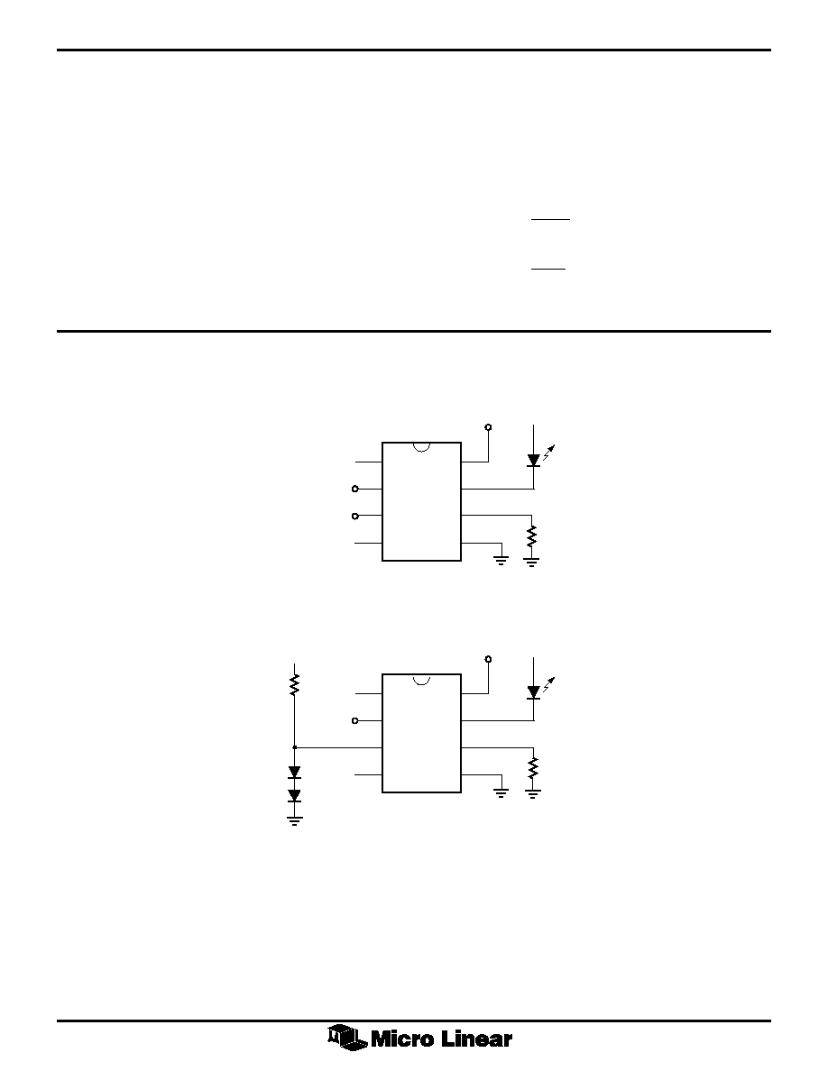
driven by a TTL or CMOS output. Figure 1b shows a circuit
implementing this technique. This circuit may degrade
pulse width distortion and should be checked for
acceptable performance in this configuration.
Output current to the LED is set by connecting the
appropriate resistance from RTSET to ground. The high
level output voltage at RTSET will be 2.0V. The current in
the external resistor will be equal to the current through
the LED. The output current with RTSET set to 26.1Wwill
be:
I
HIGH
V
RTSET
LED
(
)
=
2
(1)
I
HIGH
V
mA
LED
(
)
.
=
=
2
26 1
75
Figure 1. Typical Applications
V
CC
I
OUT
RTSET
GND
5V
VIN+
VIN≠
ECLP
ECLN
a) I
OUT
= 75mA
b) ECL-to-TTL Conversion
5V
5V
NC
NC
V
CC
I
OUT
RTSET
GND
5V
TTLIN
ECLP
ECLN
5V
NC
NC
5
ML6633
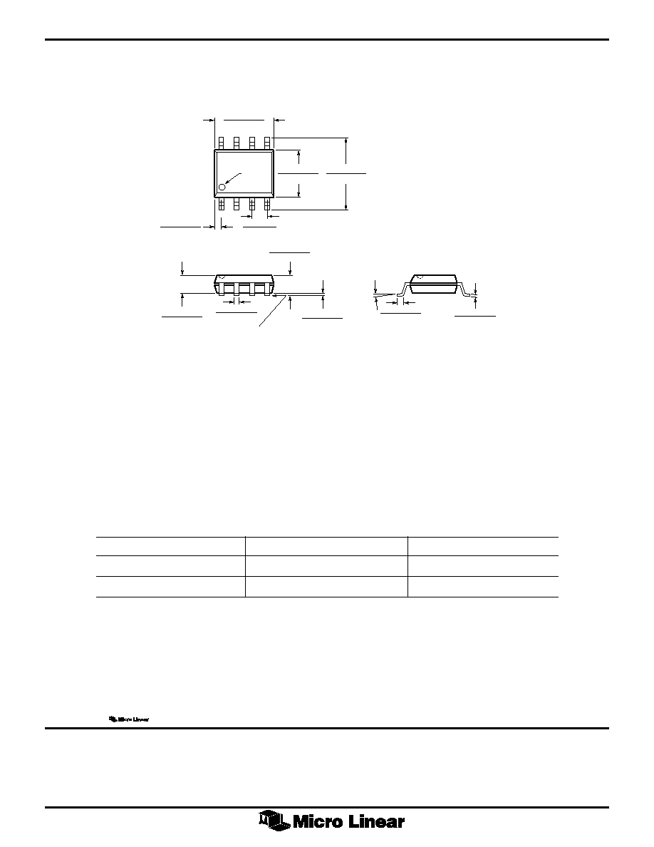
PHYSICAL DIMENSIONS
inches (millimeters)
SEATING PLANE
0.148 - 0.158
(3.76 - 4.01)
PIN 1 ID
0.228 - 0.244
(5.79 - 6.20)
0.189 - 0.199
(4.80 - 5.06)
0.012 - 0.020
(0.30 - 0.51)
0.050 BSC
(1.27 BSC)
0.015 - 0.035
(0.38 - 0.89)
0.059 - 0.069
(1.49 - 1.75)
0.004 - 0.010
(0.10 - 0.26)
0.055 - 0.061
(1.40 - 1.55)
8
0.006 - 0.010
(0.15 - 0.26)
0∫ - 8∫
1
0.017 - 0.027
(0.43 - 0.69)
(4 PLACES)
Package: S08
8-Pin SOIC
ORDERING INFORMATION
PART NUMBER
TEMPERATURE RANGE
PACKAGE
ML6633CS
0∫C to 70∫C
8-Pin SOIC (S08)
ML6633IS
≠40∫C to 85∫C
8-Pin SOIC (S08)
(Obolsete)
© Micro Linear 1998.
is a registered trademark of Micro Linear Corporation. All other trademarks are the property of their respective owners.
Products described herein may be covered by one or more of the following U.S. patents: 4,897,611; 4,964,026; 5,027,116; 5,281,862; 5,283,483;
5,418,502; 5,508,570; 5,510,727; 5,523,940; 5,546,017; 5,559,470; 5,565,761; 5,592,128; 5,594,376; 5,652,479; 5,661,427; 5,663,874; 5,672,959;
5,689,167; 5,714,897; 5,717,798; 5,742,151; 5,747,977; 5,754,012; 5,757,174; 5,767,653; 5,777,514. Japan: 2,598,946; 2,619,299; 2,704,176. Other
patents are pending.
Micro Linear reserves the right to make changes to any product herein to improve reliability, function or design. Micro Linear does not assume any
liability arising out of the application or use of any product described herein, neither does it convey any license under its patent right nor the rights of
others. The circuits contained in this data sheet are offered as possible applications only. Micro Linear makes no warranties or representations as to
whether the illustrated circuits infringe any intellectual property rights of others, and will accept no responsibility or liability for use of any application
herein. The customer is urged to consult with appropriate legal counsel before deciding on a particular application.
DS6633-01
2092 Concourse Drive
San Jose, CA 95131
Tel: (408) 433-5200
Fax: (408) 432-0295
www.microlinear.com