 | ÐлекÑÑоннÑй компоненÑ: GS001 | СкаÑаÑÑ:  PDF PDF  ZIP ZIP |
Äîêóìåíòàöèÿ è îïèñàíèÿ www.docs.chipfind.ru
© 2005 Microchip Technology Inc.
DS93001A-page 1
GS001
INTRODUCTION
As a means of reducing high energy and maintenance
costs in motor control applications, BLDC motors are
seeing a resurgence in applications where efficiency
and reliability are important. The dsPIC30F motor con-
trol devices are ideally suited to drive and control a
wide range of BLDC motor types, in a large number of
applications. Microchip has developed a number of
solutions using the dsPIC30F and BLDC motors. This
document will help you select an appropriate solution
for your BLDC motor application.
BLDC MOTOR BASICS
DC brush motors have a permanent magnet on the
stator with the motor winding on the rotor. During rota-
tion, the current in the windings is reversed using
mechanical carbon brushes and a commutator located
on the rotor. The BLDC motor has permanent magnets
on the rotor with the electrical windings on the stator.
The first obvious advantage of the BLDC motor is the
elimination of the mechanical commutator and
brushes, which significantly improves mechanical
reliability. The commutator and brushes in DC motors
also give rise to sparking, so eliminating these
components means that BLDC motors can operate in a
harsh environment. The I
2
R heat losses in the windings
of a BLDC motor are now on the stator and can be
dissipated very easily. Consequently, efficiency of the
BLDC motor is vastly improved.
There are, however, some challenges when spinning a
BLDC motor. Firstly, a revolving electrical field has to
be created in the windings, which also has to be well
aligned with the magnetic field on the rotor. The
efficiency of the BLDC motor depends largely on the
alignment of the revolving electrical field to the
magnetic field on the rotor. To sense the magnetic field,
Hall sensors are normally used. Based on the signal
presented by the Hall sensors, the windings are appro-
priately excited. As the speed of the rotor increases,
however, there is a certain amount of lag between the
voltage excitation and the current effect on the
windings due to the inductance of the windings. To
overcome this lag, the voltage is initiated a little in
advance. This phenomenon is known as phase
advance and is implemented mainly in software at high
speeds of rotation. The result of phase advance is
better efficiency in the BLDC motor operation.
Sensored BLDC Motor Control
When driving a BLDC motor, it is important to know the
position of the magnetic rotor with reference to the
stator. Most commonly, Hall effect sensors are used to
generate feedback on the rotor position. This type of
control is called sensored BLDC motor control. Most
BLDC motors have three windings. Based on the
position of the magnetic rotor, two windings are ener-
gized at a given time with each phase conducting for
120 electrical revolution degrees, resulting in six
distinct combinations of energization. This type of drive
is called "trapezoidal" or "six-step commutation".
SIX-STEP COMMUTATION
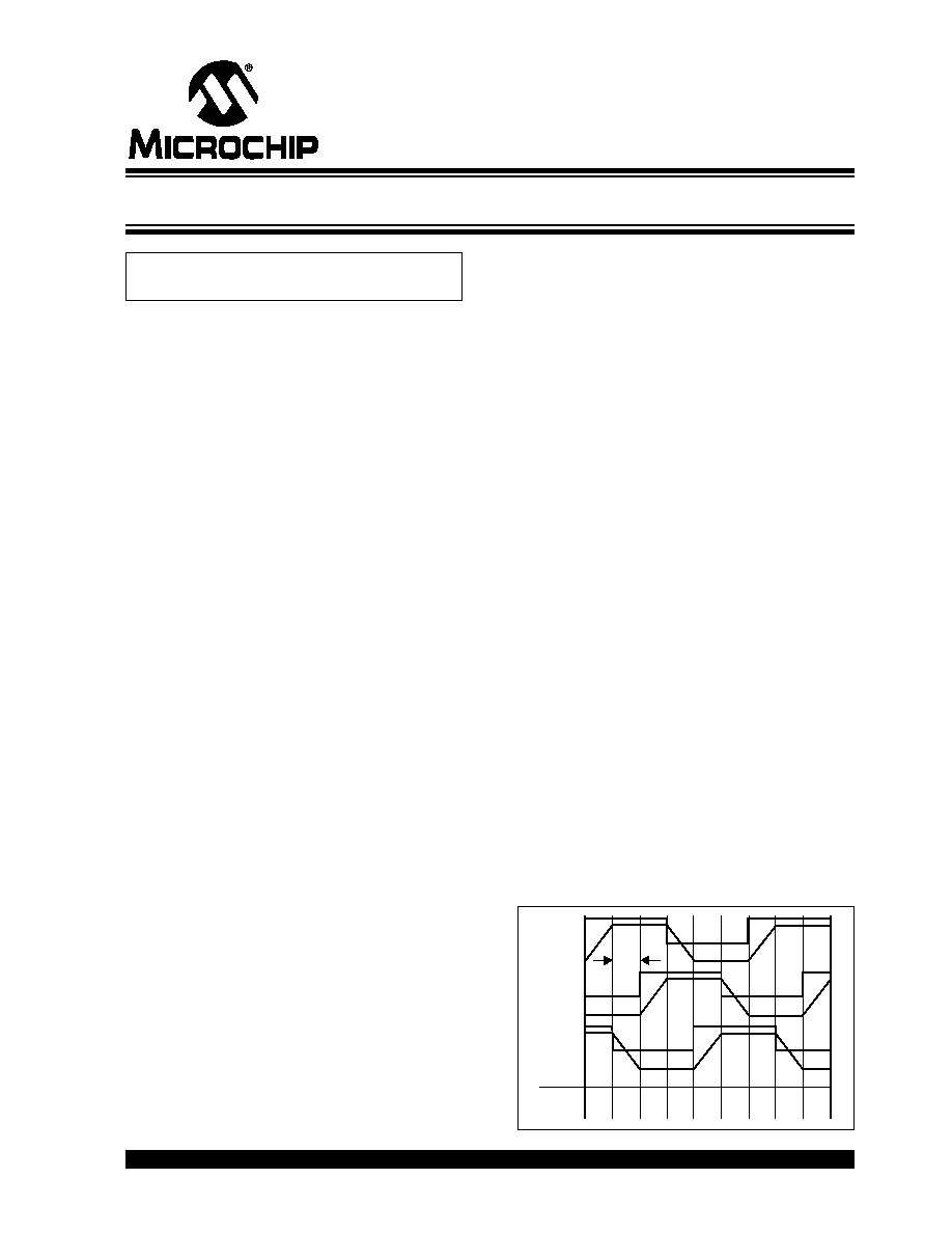
Figure 1 depicts a typical six-step commutation
scheme with the Hall sensor output overlay. Six-step
commutation offers a simple, yet efficient, method of
driving a BLDC motor. Hall A (HA), Hall B (HB) and Hall
C (HC) sense the position of the rotor with respect to
the windings, R, Y and B. Depending on the Hall sensor
reading from 1 to 6, an appropriate pair of windings is
driven high and low with the third winding not driven.
Each 360 degree electrical cycle is broken down to six
60 degree electrical sectors, in which one winding is
driven high, a second is driven low and the third is not
driven. Example: In Hall position 6 or sector 1, the R
winding is driven high while the B winding is driven low
and the Y winding is not driven. By reading the Hall
sensors, the six-step commutation algorithm can very
easily be implemented in software.
FIGURE 1:
TYPICAL SIX-STEP
COMMUTATION
Author:
Stan D'Souza
Microchip Technology Inc.
HA
R
HB
Y
HC
B
5
5
0
1
2
3
4
5
0
1
4
6
2
3
1
5
4
6
Sector
Hall
60°
Getting Started with BLDC Motors and dsPIC30F Devices
GS153
DS93001A-page 2
© 2005 Microchip Technology Inc.
DRIVING SENSORED BLDC MOTORS WITH A
SINUSOIDAL VOLTAGE
When it is rotated like a generator, a BLDC motor
creates a sinusoidal voltage output (120 degrees apart)
in all three phase windings. So the "natural" drivers for a
BLDC motor are three sinusoidal voltages at
120 degrees apart. The six-step commutation normally
works very efficiently in most BLDC applications.
However, in some applications, the DC switching of the
PWM drive voltage used in six-step commutation some-
times causes a phenomenon known as torque ripple.
Torque ripple typically manifests as a low-frequency
rumble in some systems.
An alternative to the six-step method is to feed a PWM
driven sine wave to the three phases (at 120 degrees
apart) using a Space Vector Modulation (SVM)
technique. This method is just as efficient as six-step
commutation and delivers uniform torque to the load.
Microchip is developing an application note on this
technique.
Sensorless BLDC Motor Control
Sensors add cost to a BLDC motor application. Also,
sensors need to be adjusted during the manufacturing
process. In quite a few applications, however, the need
to find the exact position of the rotor is not necessary.
Fan blowers and compressor motors are typical appli-
cations which run at a constant or limited speed range.
In these applications, the back EMF detected on the
third unexcited winding can be used to switch the PWM
commutation of the motor windings.
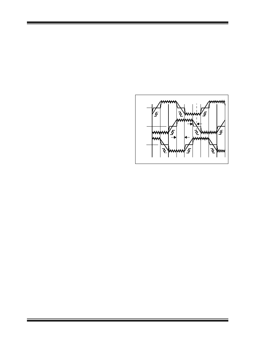
Figure 2 shows a typical sensorless commutation
diagram. In this method, the back EMF voltage on the
winding that is not driven in each sector is monitored.
When this voltage crosses the imaginary "half-point" or
"zero-crossing" line, zero crossing is detected. The
algorithm now knows that it is in the center of the sector
and has 30 electrical degrees remaining to do the next
commutation. The time taken for each sector
(60 degrees) is known as, say T60. When the zero-
crossing point is detected, a timer is loaded with half
the value of T60. When this timer times out, an interrupt
is generated and the next winding commutation is
implemented. This method of control is called
sensorless control of a BLDC motor.
For example, in Sector 1, the Y winding is monitored for
zero crossing. When that transition occurs, the timer is
loaded with half the T60 time in a timer. When that timer
times out, the windings are commutated as described
earlier. That is, Y is driven high, B is kept at low and R
is not driven.
Microchip has developed two application notes on sen-
sorless BLDC control:
AN901, "Using the dsPIC30F for
Sensoreless BLDC Control" and AN992, "Sensorless
BLDC Motor Control Using dsPIC30F2010".
FIGURE 2:
TYPICAL SENSORLESS
COMMUTATION
5
5
0
0
1
1
2
3
4
SECTOR
0
0
0
R
Y
B
T60
T30

© 2005 Microchip Technology Inc.
DS93001A-page 3
GS153
dsPIC30F APPLICATION NOTES
The following are some applications notes on BLDC
motor control with the dsPIC30F that will help you jump
start your BLDC motor control project
AN957, "Sensored BLDC Motor Control
Using dsPIC30F2010"
This application note describes a simple open and
closed-loop solution to control a sensored BLDC motor
using a 28-pin dsPIC30F2010. The solution described
uses the six-step commutation method described
above to rotate and control the sensored BLDC motor.
The hardware platform used is the PICDEMTM MC LV
Board. With minor modifications, this application note
can be used with any other hardware platform from
Microchip (see the following section on motor control
boards). The firmware, with minor modifications, can
also be used with any motor control dsPIC30F device.
The dsPIC30F2010 is ideally suited for this application
due to on-chip availability of the motor control PWM,
Hall sensor and QEI input modules and the ability of the
DSP engine to compute multiple PID control loops.
AN901, "Using the dsPIC30F for
Sensorless BLDC Control"
This application note describes how to implement
sensorless control of a BLDC motor using the back EMF
detection technique mentioned above. The back EMF
voltage is attenuated and fed to the ADC inputs of the
dsPIC
®
Digital Signal Controller (DSC). The high-speed
ADC is then used to detect the zero crossing. This tech-
nique provides a very efficient control method for starting
and running a sensorless BLDC motor with a minimum
of components. The hardware used is a dsPICDEMTM
MC1 Motor Control Development Board used in con-
junction with either a dsPICDEM MC1L 3-Phase Low-
Voltage Power module or a dsPICDEM MC1H 3-Phase
High-Voltage Power module.
A dsPIC30F6010 device is used on the MC1 board in
this application. The application note describes in detail
how to start and run a sensorless BLDC motor. The
control method, however, is general enough to work
with any BLDC motor available in the market. Details
are provided to assist you in configuring the 45 param-
eters needed to start and run the BLDC motor. All 45 of
these user parameters can be set using the LCD and
push buttons available on the MC1 development board.
The firmware supports four different control modes and
two starting modes. The hardware drive section is
connected via a 37-pin D-type connector to either a
high-voltage or low-voltage power module, which
allows for BLDC motors that can operate in the voltage
range from 10 to 400 VDC. The firmware can also be
modified to work with any motor control dsPIC30F
device.
The dsPIC30F6010 is ideally suited for this application
because it includes on-chip motor control PWM, Hall
sensor and QEI input modules, along with a fast ADC
required to sample the back EMF and detect zero
crossing. A powerful DSP engine is available to
compute multiple PID control loops.
AN992, "Sensorless BDLC Motor Control
Using dsPIC30F2010"
This application note takes the application described in
AN901 one step further and provides a low-cost, yet
efficient, implementation on the smallest dsPIC30F
motor control device available, namely the 28-pin
dsPIC30F2010 with 12 Kbytes of program memory and
512 bytes of RAM. The hardware is simplified and uses
the stand-alone PICDEMTM MC LV board as the
hardware platform.
Because the PICDEM MC LV board has no LCD and
the dsPIC30F2010 has limited I/O, the 45 user param-
eters are set using a PC via the serial port and a
HyperTerminal link.
The PICDEM MC LV only supports voltages from 10 to
40 VDC, hence, only low-voltage BLDC motors are
able to run on this board. However, the technique used
in this application can be extrapolated. If higher voltage
and current drivers are provided to support higher volt-
age and current, then a similar, but modified hardware
can be used to run BLDC motors from 40V to 400V DC.
The dsPIC30F2010 is ideally suited for this application.
It includes on-chip motor control PWM, Hall sensor and
QEI input modules, along with a fast ADC to sample the
back EMF and detect zero crossing. A powerful DSP
engine is available to compute multiple PID control
loops.
GS153
DS93001A-page 4
© 2005 Microchip Technology Inc.
dsPIC30F HARDWARE MODULES TO
CONTROL BLDC MOTORS
Micorchip offers a number of hardware tools to help you
implement your own BLDC motor control solution.
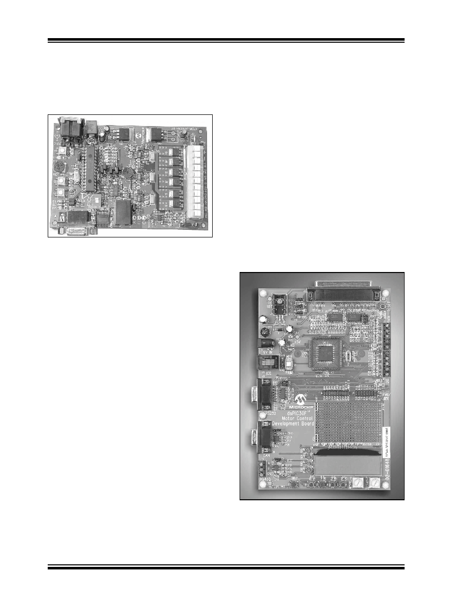
FIGURE 3:
PICDEMTM MC LV BOARD
PICDEM MC LV Board
This board offers a self-contained, low-voltage platform
(Figure 3) that supports all 28-pin motor control
dsPIC30F devices, including the dsPIC30F2010,
dsPIC30F3010 and the dsPIC30F4012. Hardware sup-
port for sensored, as well as sensorless, BLDC motors
is available on this board. The factory shipped board
supports a motor voltage of 24V; however, the
hardware can support voltages from 10V to 40V at
motor currents of up to 4 Amps.
A serial port is available to communicate with an
external source. An MPLAB
®
ICD 2 In-Circuit Debug-
ger connection is available for programming and
debugging purposes. A potentiometer is available for
speed control, along with two switches for start/stop
control.
On-board power drivers support direct drive to the
BLDC motor. A low-side power resistor supplies current
and Fault feedback to the dsPIC DSC. The "
PICDEMTM
MC LV Development Board User's Guide" (DS51554)
provides details on the use of this board.
dsPICDEM MC1 Motor Control
Development Board
The dsPICDEM MC1 Motor Control Development
Board (Figure 4), is a general purpose development
board that uses a dsPIC30F6010 to control a wide
range of motor control applications, including sensored
and sensorless BLDC motors. Serial RS-232 and CAN
ports are supported, along with an ICD 2 In-Circuit
Debugger connection for programming and debugging
purposes.
A two-lines by 20-character LCD is used along with four
LEDs for display purposes. Four push buttons and two
potentiometers are available for data entry and feed-
back. Spare analog and digital pins are made available
on two header banks.
No drivers are available on the board, so the MC1
board must be connected to an external drive system.
A 37-pin D-type connector is used to connect the MC1
board to a dsPICDEM MC1H 3-Phase High-Voltage
module (Figure 5) or dsPICDEM MC1L 3-Phase Low-
Voltage module (Figure 6). The D-type connector
connects to external circuitry via opto isolators, thus
allowing for a safe, electrically isolated drive to high
voltage (400 VDC).
The dsPICDEM MC1 Motor Control Development
Board can be used with a dsPICDEM MC1H 3-Phase
High-Voltage Power module to drive a high-voltage
BLDC motor. Refer to the "
dsPICDEMTM MC1 Motor
Control Development Board User's Guide" (DS70098)
for full details on the capabilities and functions
available on this board.
FIGURE 4:
dsPICDEMTM MC1 MOTOR
CONTROL DEVELOPMENT
BOARD
[Insert photo of dsPICDEM MC1 Board]
© 2005 Microchip Technology Inc.
DS93001A-page 5
GS153
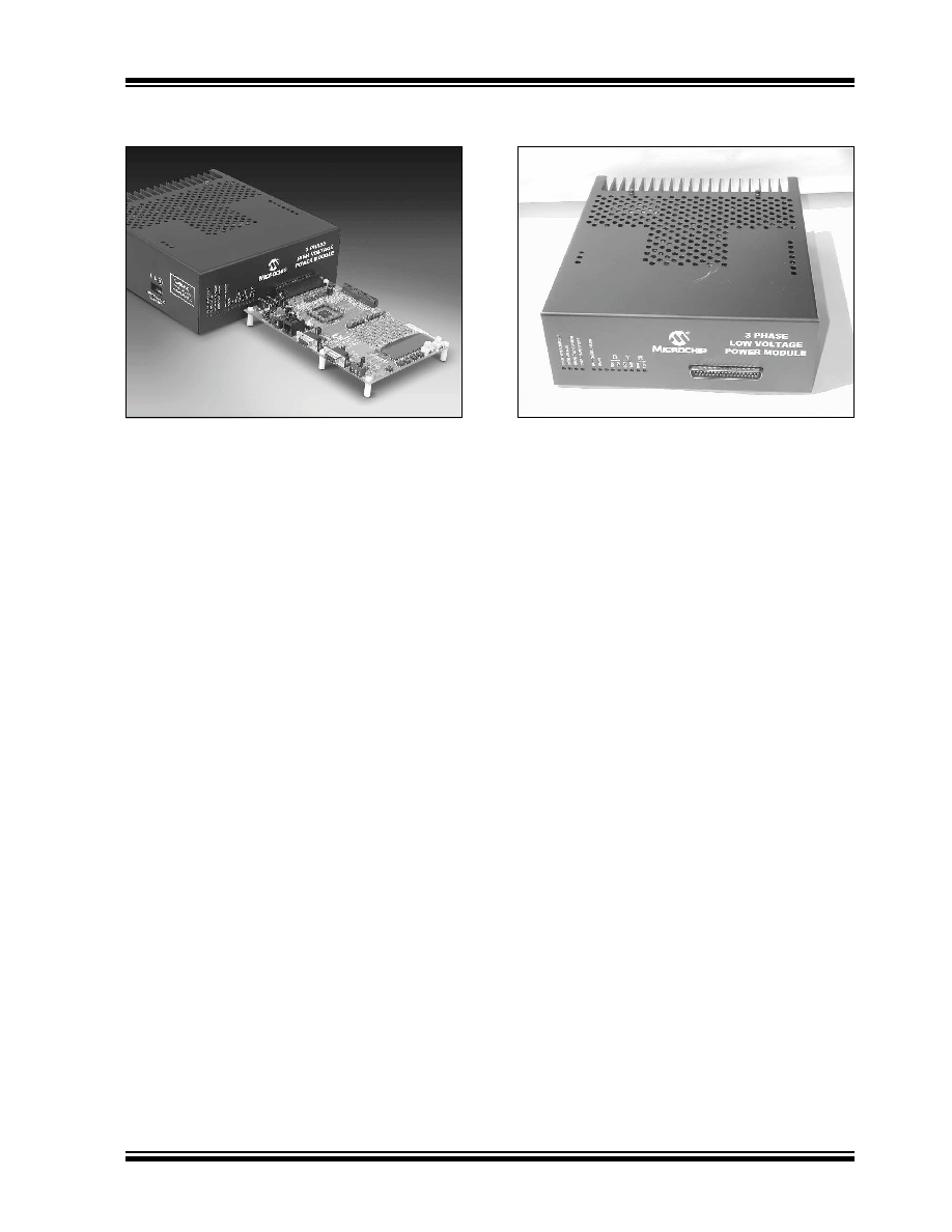
FIGURE 5:
dsPICDEMTM MC1H 3-
PHASE HV MODULE
dsPICDEM MC1H 3-Phase High-Voltage
Power Module
The high-voltage module (Figure 5) connects to an
MC1 board to form a high-voltage BLDC motor control
system. The dsPICDEM MC1H 3-Phase High-Voltage
Power module offers high-voltage isolation, as well as
Fault, overcurrent and overvoltage protection. Each
phase is monitored with fast current sensors and a
robust latching network to disable the outputs in case
any Fault condition occurs. This protection is neces-
sary during code development and prevents accidental
destruction of the drive circuitry due to inadvertent
software issues.
The high-voltage module rectifies a single-phase wall
input voltage of 110 VAC to generate a DC bus voltage
of 165 VDC. Alternatively, it can also rectify an input
wall voltage of 220 VAC to get a DC bus voltage of
330 VDC. This DC bus voltage is then converted to
drive a 3-phase motor.
The hardware can be used to drive ACIM and BLDC
motors. For complete details on the features and
capabilities of this module, refer to the "
dsPICDEMTM
MC1H 3-Phase High-Voltage Power Module User's
Guide" (DS70096).
FIGURE 6:
dsPICDEMTM MC1L 3-PHASE
LV MODULE
dsPICDEM MC1L 3-Phase Low-Voltage
Power Module
The low-voltage module (Figure 6) connects to an MC1
board to form a low-voltage BLDC motor control
system. The dsPICDEM MC1L 3-Phase Low-Voltage
Power module offers voltage isolation, along with Fault,
overcurrent and overvoltage protection. Each phase is
monitored with fast current sensors and a robust latch-
ing network to disable the outputs in case any Fault
condition occurs. This protection is necessary during
code development and prevents accidental destruction
of the drive circuitry due to inadvertent software issues.
DC voltage is supplied externally from a power supply.
This DC bus voltage is then converted to drive a 3-phase
motor.
The hardware can drive 3-phase low-voltage BLDC
motors. For more details on the features and cap-
abilities of this module, refer to the
"dsPICDEMTM
MC1L 3-Phase Low-Voltage Power Module User's
Guide (DS70097).