CEA 3207A
June/2002
PRODUCT INFORMATION
CEA 3207A
ARM7-BASED CAR ENTERTAINMENT CONTROLLER
The CEA 3207A is the first device of
Micronas' 32-bit Car Entertainment Control-
ler family based on an ARM7TDMI CPU
core.
Like the already available CDC 3207G, the
CEA 3207A is part of the LEAP family con-
cept (Low Emission Automotive Processor).
The microcontroller with its ARM7TDMI
RISC CPU core allows two states of opera-
tion: ARM state with 32-bit instructions and
THUMB state with 16-bit instructions.
It is suited for entertainment-related appli-
cations like car radio or navigation systems.
The current version CEA 3207A offers
32 kBytes of SRAM, 512 kBytes of Flash,
and 8 kBytes of boot ROM. Communication
is possible via two FullCAN modules, two
I
2
C modules and two UART or SPI modules
each. Due to its scalable architecture, fur-
ther derivatives can be obtained within
short lead time. An upgrade version with
1 MByte Flash and up to 64 kBytes RAM,
as well as a downgrade version with
256 kBytes Flash and 16 kBytes RAM in the
same package is planned. All devices have
the patented built-in ERM (EMI Reduction
Module) and are operated on a single 5-V
power supply.
Features
512 kBytes Flash ROM
32 kBytes SRAM
8 kBytes boot ROM
Four CPU operation modes
(Deep Slow, Slow, Fast, PLL)
PLL circuitry delivering up to 50 MHz
4- to 5-MHz oscillator
EMI reduction module (ERM)
Digital watchdog
Central clock divider
Interrupt controller with 40 inputs and
16 priority levels
Six port interrupts
Regulator input supervision for reset/
alarm
Clock and supply supervision
16-channel 10-bit ADC
Two comparators
ADC reference (1 internal, 3 external)
48
◊
4 LCD module (optional)
Three DMA channels
Two UARTs, two SPIs
Two CAN modules with 512 Bytes each
of object RAM according to Bosch speci-
fication V2.0B (32 message objects)
DigitBus master module
Two I
2
C master modules
Six PWM modules (configurable as
2
◊
8 bit or 1
◊
16 bit)
Phase frequency modulator
Sound generator with auto decay
Two SW-selectable clock outputs
16-bit free-running counter with six cap-
ture/compare modules
1
◊
16 bit timer and 4x8 bit timer
JTAG interface
-
40 to +105 ∞C case temperature range
Single 3.5 V to 5.5 V supply voltage
(limited I/O performance below 4.5 V)
Up to 100 GPIOs
128-pin PQFP package with 0.5 mm pin
pitch
PRODUCT INFORMATION
CEA 3207A
June/2002
All information and data contained in this product information are without any commitment, are not to be
considered as an offer for conclusion of a contract, nor shall they be construed as to create any liability.
Product or development sample availability and delivery are exclusively subject to our respective order
confirmation form. By this publication, Micronas GmbH does not assume responsibility for patent infringe-
ments or other rights of third parties which may result from its use.
Hans-Bunte-Strasse 19
D-79108 Freiburg (Germany)
P.O. Box 840
D-79008 Freiburg (Germany)
Tel. +49-761-517-0
Fax +49-761-517-2174
E-mail: docservice@micronas.com
www.micronas.com
Micronas GmbH's prior written consent must be
obtained for reprinting.
Edition June 5, 2002
Order No. 6251-600-1PI
DSP
CD-ROM
Tuner
DAC
3550A
CEA
32xxA
ARM7
A
1
2
3
4 7
1
2 4 36 , 56
4
7
/
K
7
I
2
S
I
2
C
Subwoofer
6261-102-1x
Display
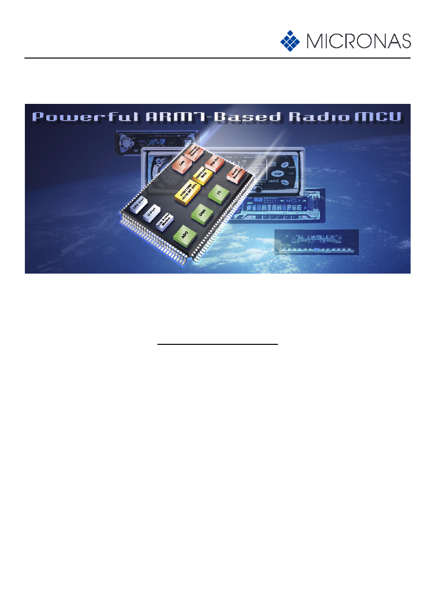
Application
The CEA 3207A targets infotainment appli-
cations with a need for high performance. It
serves as controller, as well as interface to
signal processing units.
Due to its scalable architecture, the
CEA 3207A can be upgraded with more
memory, CAN controller, DSP, and graphi-
cal functions. The application can also be
upgraded towards multistandard decoding
capabilities (MP3, AAC, WMA) using Micro-
nas' MAS 35xx family devices.
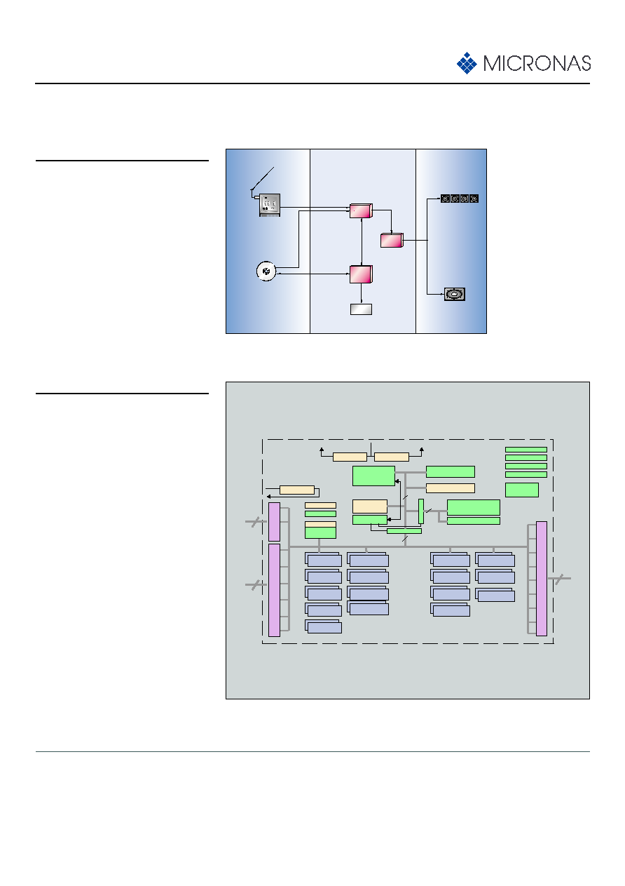
System Architecture
The Car Entertainment Controller
CEA 3207A contains an embedded ARM7-
TDMI processor which operates at a maxi-
mum clock frequency of 50 MHz.
Internally, this device works with different
supply voltages: 2.5 V for the core and
3.3 V for the Flash memory.
The system is scalable in terms of Flash
memory, RAM, CAN, and the number of
peripherals and can be expanded up to
1 MByte of Flash memory.
The built-in ERM delivers superb EMI
results reducing the peak values by up to
10 dB
µ
V.
Fig. 2: Block diagram of the CEA 3207A
VREFINT
VREF
AVDD
AVSS
BVDD
HP
o
r
t
s
UP
o
r
t
s
PP
o
r
t
s
UARTS
2
◊
UART
UARTS
2
◊
SPI
UARTS
2
◊
CAN
UARTS
DIGITBus
UARTS
2
◊
I≤C Bus
UARTS
LCD Control
(optional)
UARTS
Audio Module
UARTS
Clock Out 0,1
UARTS
16- Bit CCC 0
UARTS
UARTS
16- Bit CCC 1
UARTS
JTAG Interface
Test / Debug
Reset
Test
Watchdog Clock
PLL
10-Bit ADC
8
ARM7TDMI
CPU
DMA Contr.
40-Input
Interrupt Controller
32 kB SRAM
512 kB Flash
8 kB Boot
ROM
Bridge
Br
id
ge
16
32
Bus Controller
P0.6 Comp
Wait Comp
VDD
VSS
UVDD
UVSS
FVDD
FVSS
3.3-V Reg.
2.5-V Reg.
2.5-V Reg.
UART S
UA
UARTS
ERM
(EMI Reduction Module)
16
52
32
CAPCOM 0,1,2,3
CAPCOM 4, 5
Bandgap Ref.
UART S
4
◊
8-Bit Timer
1
◊
16-Bit Timer
6
◊
8/16-Bit PWM
Fig. 1: Example application: CD-ROM-based car radio