VPC 323xD, VPC 324xD
ADVANCE INFORMATION
2
Micronas
Contents
Page
Section
Title
5
1.
Introduction
5
1.1.
System Architecture
6
1.2.
Video Processor Family
7
1.3.
VPC Applications
8
2.
Functional Description
8
2.1.
Analog Video Front-End
8
2.1.1.
Input Selector
8
2.1.2.
Clamping
8
2.1.3.
Automatic Gain Control
8
2.1.4.
Analog-to-Digital Converters
8
2.1.5.
Digitally Controlled Clock Oscillator
8
2.1.6.
Analog Video Output
9
2.2.
Adaptive Comb Filter
9
2.3.
Color Decoder
10
2.3.1.
IF-Compensation
10
2.3.2.
Demodulator
10
2.3.3.
Chrominance Filter
11
2.3.4.
Frequency Demodulator
11
2.3.5.
Burst Detection / Saturation Control
11
2.3.6.
Color Killer Operation
11
2.3.7.
Automatic standard recognition
12
2.3.8.
PAL Compensation/1-H Comb Filter
13
2.3.9.
Luminance Notch Filter
13
2.3.10.
Skew Filtering
13
2.4.
Component Interface Processor CIP
13
2.4.1.
Component Analogue Front End
13
2.4.2.
Matrix
13
2.4.3.
Component YC
r
C
b
Control
14
2.4.4.
Softmixer
14
2.4.4.1.
Static Switch Mode
14
2.4.4.2.
Static Mixer Mode
14
2.4.4.3.
Dynamic Mixer Mode
15
2.4.5.
4:4:4 to 4:2:2 Downsampling
15
2.4.6.
Fast Blank and Signal Monitoring
15
2.5.
Horizontal Scaler
15
2.5.1.
Horizontal Lowpass-filter
16
2.5.2.
Horizontal Prescaler
16
2.5.3.
Horizontal Scaling Engine
16
2.5.4.
Horizontal Peaking-filter
17
2.6.
Vertical Scaler
17
2.7.
Contrast and Brightness
17
2.8.
Blackline Detector
17
2.9.
Control and Data Output Signals
17
2.9.1.
Line-Locked Clock Generation
18
2.9.2.
Sync Signals
18
2.9.3.
DIGIT3000 Output Format

Contents, continued
Page
Section
Title
ADVANCE INFORMATION
VPC 323xD, VPC 324xD
Micronas
3
18
2.9.4.
Line-Locked 4:2:2 Output Format
18
2.9.5.
Line-Locked 4:1:1 Output Format
18
2.9.6.
ITU-R 656 Output Format
20
2.9.7.
Output Code Levels
20
2.9.8.
Output Ports
20
2.9.9.
Test Pattern Generator
20
2.10.
PAL+ Support
20
2.10.1.
Output Signals for PAL+/Color+ Support
22
2.11.
Video Sync Processing
24
2.12.
Picture in Picture (PIP) Processing and Control
24
2.12.1.
Configurations
25
2.12.2.
PIP Display Modes
25
2.12.3.
Predefined Inset Picture Size
28
2.12.4.
Acquisition and Display Window
28
2.12.5.
Frame and Background Color
28
2.12.6.
Vertical Shift of the Main Picture
28
2.12.7.
Free Running Display Mode
28
2.12.8.
Frame and Field Display Mode
29
2.12.9.
External Field Memory
30
3.
Serial Interface
30
3.1.
I
2
C-Bus Interface
30
3.2.
Control and Status Registers
49
3.2.1.
Calculation of Vertical and East-West Deflection Coefficients
49
3.2.2.
Scaler Adjustment
51
4.
Specifications
51
4.1.
Outline Dimensions
51
4.2.
Pin Connections and Short Descriptions
54
4.3.
Pin Descriptions (pin numbers for PQFP80 package)
57
4.4.
Pin Configuration
58
4.5.
Pin Circuits
59
4.6.
Electrical Characteristics
59
4.6.1.
Absolute Maximum Ratings
59
4.6.2.
Recommended Operating Conditions
60
4.6.3.
Recommended Crystal Characteristics
61
4.6.4.
Characteristics
61
4.6.4.1.
Characteristics, 5 MHz Clock Output
61
4.6.4.2.
Characteristics, 20 MHz Clock Input/Output, External Clock Input (XTAL1)
61
4.6.4.3.
Characteristics, Reset Input, Test Input, VGAV Input, YCOEQ Input
62
4.6.4.4.
Characteristics, Power-up Sequence
63
4.6.4.5.
Characteristics, FPDAT Input/Output
63
4.6.4.6.
Characteristics, I
2
C Bus Interface
64
4.6.4.7.
Characteristics, Analog Video and Component Inputs
64
4.6.4.8.
Characteristics, Analog Front-End and ADCs
66
4.6.4.9.
Characteristics, Analog FB Input
67
4.6.4.10.
Characteristics, Output Pin Specification

VPC 323xD, VPC 324xD
ADVANCE INFORMATION
4
Micronas
Contents, continued
Page
Section
Title
69
4.6.4.11.
Characteristics, Input Pin Specification
70
4.6.4.12.
Characteristics, Clock Output Specification
71
5.
Application Circuit
72
5.1.
Application Note: VGA mode with VPC 3215C
73
5.2.
Application Note: PIP Mode Programming
73
5.2.1.
Procedure to Program a PIP Mode
73
5.2.2.
I
2
C Registers Programming for PIP Control
75
5.2.3.
Examples
75
5.2.3.1.
Select Predefined Mode 2
75
5.2.3.2.
Select a Strobe Effect in Expert Mode
76
5.2.3.3.
Select Predefined Mode 6 for Tuner Scanning
78
6.
Data Sheet History
ADVANCE INFORMATION
VPC 323xD, VPC 324xD
Micronas
5
Comb Filter Video Processor
1. Introduction
The VPC 323xD/324xD is a high-quality, single-chip
video front-end, which is targeted for 4:3 and 16:9, 50/
60 and 100/120 Hz TV sets. It can be combined with
other members of the DIGIT3000 IC family (such as
DDP 33x0A/B, TPU 3040) and/or it can be used with
3rd-party products.
The main features of the VPC 323xD/324xD are
≠ high-performance adaptive 4H comb filter Y/C sepa-
rator with adjustable vertical peaking
≠ multi-standard color decoder PAL/NTSC/SECAM
including all substandards
≠ four CVBS, one S-VHS input, one CVBS output
≠ two RGB/YC
r
C
b
component inputs, one Fast Blank
(FB) input
≠ integrated high-quality A/D converters and associ-
ated clamp and AGC circuits
≠ multi-standard sync processing
≠ linear horizontal scaling (0.25 ... 4), as well as
non-linear horizontal scaling `panorama vision'
≠ PAL+ preprocessing (VPC 323xD)
≠ line-locked clock, data and sync, or 656-output inter-
face (VPC 323xD)
≠ display and deflection control (VPC 324xD)
≠ peaking, contrast, brightness, color saturation and
tint for RGB/ YC
r
C
b
and CVBS/ S-VHS
≠ high-quality soft mixer controlled by Fast Blank
≠ PIP processing for four picture sizes (
, or
of
normal size) with 8 bit resolution
≠ 15 predefined PIP display configurations and expert
mode (fully programmable)
≠ control interface for external field memory
≠ I
2
C-Bus Interface
≠ one 20.25 MHz crystal, few external components
≠ 80-pin PQFP package
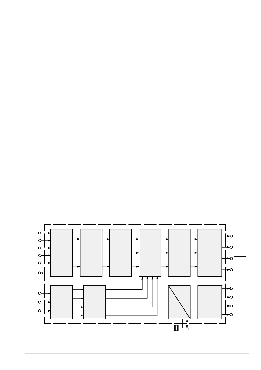
1.1. System Architecture
Fig.1≠1 shows the block diagram of the video proces-
sor
Fig. 1≠1: .Block diagram of the VPC 323xD
1
4
---
1
9
---
1
16
------
, ,
1
36
---
Mixer
CIN
VIN1
VIN2
VIN3
VIN4
VOUT
Adaptive
Comb
Color
Decoder
Output
Formatter
Matrix
Filter
2D Scaler
Panorama
Mode
PIP
ITU-R 656
ITU-R 601
Memory
Control
Sync
AGC
Contrast
Saturation
Brightness
Tint
NTSC
PAL
NTSC
PAL
SECAM
+
Clock
Generation
CrCb
OUT
Y OUT
YCOE
FIFO
CNTL
H Sync
V Sync
AVO
I
2
C Bus
20.25 MHz
RGB/
FB
Y
Cb
Cr
Y
Cb
Cr
Y/G
U/B
Y
Cb
Cr
LL Clock
Saturation
Tint
Analog
Front-end
Contrast
Brightness
Peaking
Clock
Gen.
I
2
C Bus
V/R
FB
FB
YCrCb
RGB/
YCrCb
2
◊
ADC
Analog
Component
Front-End
4 x ADC
Processing