 | –≠–ª–µ–∫—Ç—Ä–æ–Ω–Ω—ã–π –∫–æ–º–ø–æ–Ω–µ–Ω—Ç: 42144 | –°–∫–∞—á–∞—Ç—å:  PDF PDF  ZIP ZIP |

Micropac Industries cannot assume any responsibility for any circuits shown or represent that they are free from patent infringement.
Micropac reserves the right to make changes at any time in order to improve design and to supply the best product possible.
MICROPAC INDUSTRIES, INC.
MICROCIRCUITS PRODUCTS DIVISION ∑ 905 E. Walnut St., Garland, TX 75040 ∑ (972) 272-3571 ∑ Fax (972) 494-2281
www.micropac.com
E-MAIL: HYBRIDSALES @ MICROPAC.COM 5/22/02
Pg. 1 of 5
PRELIMINARY DATA SHEET
42144
RADIATION TOLERANT FULL BRIDGE
POWER DRIVER HYBRID
FOR 3-PHASE BRUSHLESS DC MOTORS
Mii
MICROCIRCUITS PRODUCTS
DIVISION
Features:
∑ Designed for 100 krad(Si) Total Dose
∑ Hermetically Sealed Package
∑ 2A Peak Output Current
∑ Built-in High-Side Gate Drive Circuit
∑ N- and P-channel MOSFETs for Ease of Drive
∑ Electrically Isolated Package
∑ Interface Directly with UC1625 Motor Controller
Applications:
∑ 3-Phase BLDC Motor Control
∑ Fin Actuator Control
∑ Antenna Deployment Control
∑ Mirror Position Control
∑ X-Y Table Control
∑ Gimbal Stabilization Platform
∑ Guidance System
DESCRIPTION
The 42144 Full Bridge Power Driver Hybrid is designed for high reliability applications in harsh environment. This
compact design offers a full-bridge power driver stage for three-phase brushless DC motor applications. The
circuit is electrically isolated from the metal case for ease of mounting in the system. The hybrid package provides
two mounting ears for ease of assembly and low thermal resistance path. Each phase contains a high-side gate
drive circuit for the P-channel power MOSFET, a series gate resistor for the low-side N-channel power MOSFET,
and three Schottky diodes. The high-side gate drive circuit accepts an open-collector signal of the application
controller circuit and generates required gate voltage to operate the high-side MOSFET. The low-side gate resistor
will prevent any oscillations and minimize ringing. As an option, a Schottky diode in series with the low-side
MOSFET insures that braking current will not flow backward through the N-channel MOSFET. Sources of the low-
side MOSFETs are terminated individually allowing user to configure the desired current sensing option.
Micropac 42144 Full Bridge Power Driver Hybrid employed selected components that are capable to perform in
radiation environment with minimum degradation. The hybrid will perform over the full military temperature range
of ≠55∞C to +125∞C. It is fabricated using DSCC certified manufacturing processes that are fully in compliance with
MIL-PRF-38534. This device is available in a variety of quality levels from COTS to Class K including any custom
screening requirements. The basic data sheet part is environmentally screened to H level in accordance with
Table C-IX of MIL-PRF-38534.
ABSOLUTE MAXIMUM RATINGS
Supply Voltage, V
M
................................................................................................................................................60 VDC
Peak Pulsed Output Current (< 1% duty cycle).................................................................................................... 5 A
Dielectric Withstanding Voltage......................................................................................................................... 500 VDC
Storage Temperature Range ................................................................................................................. -65∫C to +150∫C
Operating Junction Temperature.......................................................................................................... -55∫C to +150∫C
Lead Solder Temperature for 10 seconds ............................................................................................................. 300∫C
Junction-to case thermal resistance,
J-C
.........................................................................................................TBD ∫C/W
Case Temperature................................................................................................................................................... 125∫C
WEIGHT: .....................................................................................................................................TBD grams (typical)

Micropac Industries cannot assume any responsibility for any circuits shown or represent that they are free from patent infringement.
Micropac reserves the right to make changes at any time in order to improve design and to supply the best product possible.
MICROPAC INDUSTRIES, INC.
MICROCIRCUITS PRODUCTS DIVISION ∑ 905 E. Walnut St., Garland, TX 75040 ∑ (972) 272-3571 ∑ Fax (972) 494-2281
www.micropac.com
E-MAIL: HYBRIDSALES @ MICROPAC.COM 5/22/02
Pg. 2 of 5
PRELIMINARY DATA SHEET
42144
Full Bridge Power Driver Hybrid
RECOMMENDED OPERATING CONDITIONS:
Parameter Symbol
Min.
Max.
Units
Motor Supply Voltage
V
M
50 VDC
Continuous Output Current
I
O (ON)
2
A
Input Voltage (off)
V
F (OFF)
0 1
VDC
Operating Case Temperature
T
C
-55
125 ∞C
ELECTRICAL SPECIFICATIONS
T
C
= 25∞C unless otherwise specified
Switching Characteristics (N-Channel, lower switches)
CHARACTERISTICS SYM. MIN. TYP. MAX. UNIT TEST
CONDITIONS
Turn-On Delay Time
t
d(ON)
25 ns
V
M
= 24VDC, I
M
= 2A,
Rise Time
t
r
55
ns
V
M
= 24VDC, I
M
= 2A
Turn-Off Delay Time
t
d(OFF)
55 ns
V
M
= 24VDC, I
M
= 2A
Fall Time
t
f
45
ns
V
M
= 24VDC, I
M
= 2A
On-State Resistance
R
DS(ON)
0.20
ohms
V
M
= 24VDC, I
M
= 2A
Switching Characteristics (P-Channel, upper switches)
CHARACTERISTICS SYM. MIN. TYP. MAX. UNIT TEST
CONDITIONS
Turn-On Delay Time
t
d(ON)
30 ns
V
M
= 24VDC, I
M
= 2A
Rise Time
t
r
50
ns
V
M
= 24VDC, I
M
= 2A
Turn-Off Delay Time
t
d(OFF)
70 ns
V
M
= 24VDC, I
M
= 2A
Fall Time
t
f
70
ns
V
M
= 24VDC, I
M
= 2A
On-State Resistance
R
DS(ON)
0.35
ohms
V
M
= 24VDC, I
M
= 2A
Diode Characteristics
CHARACTERISTICS SYM. MIN. TYP. MAX. UNIT TEST
CONDITIONS
Forward Voltage
V
F
0.6
VDC
V
M
= 24VDC, I
M
= 2A
Forward Time
t
r
TBD
ns
V
M
= 24VDC, I
M
= 2A
Reverse Recovery Time
t
rr
TBD
ns
V
M
= 24VDC, I
M
= 2A
Micropac Industries cannot assume any responsibility for any circuits shown or represent that they are free from patent infringement.
Micropac reserves the right to make changes at any time in order to improve design and to supply the best product possible.
MICROPAC INDUSTRIES, INC.
MICROCIRCUITS PRODUCTS DIVISION ∑ 905 E. Walnut St., Garland, TX 75040 ∑ (972) 272-3571 ∑ Fax (972) 494-2281
www.micropac.com
E-MAIL: HYBRIDSALES @ MICROPAC.COM 5/22/02
Pg. 3 of 5
PRELIMINARY DATA SHEET
42144
Full Bridge Power Driver Hybrid
High Side Input Specifications (
Open Collector)
PARAMETERS MIN
MAX
UNIT
TEST
CONDITIONS
V
CE(OFF)
TBD
TBD
VDC
V
CE(SAT)
TBD
TBD
VDC
@
I
M
= 2A
Rise Time
TBD
TBD
ns
Fall Time
TBD
TBD
ns
Low Side Input Specifications
PARAMETERS MIN
MAX
UNIT
TEST
CONDITIONS
V
in
(Hi)
15
VDC
V
in
(Lo)
0
0.5
VDC
I
in
(Hi)
300
mA
I
in
(Lo)
-300
mA
Rise Time
TBD
ns
Fall Time
TBD
ns
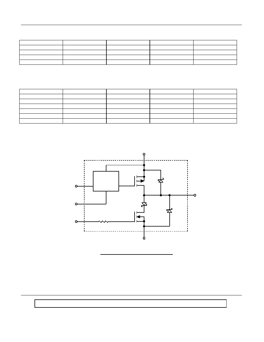
EQUIVALENT SCHEMATIC PER PHASE
PH
GND
High Side
Gate Drive
Circuit
PL
VM
Q1
CR1
CR2
Q2
CR3
n
R
RG
ÿn
n
n
Figure 1. Block Diagram

Micropac Industries cannot assume any responsibility for any circuits shown or represent that they are free from patent infringement.
Micropac reserves the right to make changes at any time in order to improve design and to supply the best product possible.
MICROPAC INDUSTRIES, INC.
MICROCIRCUITS PRODUCTS DIVISION ∑ 905 E. Walnut St., Garland, TX 75040 ∑ (972) 272-3571 ∑ Fax (972) 494-2281
www.micropac.com
E-MAIL: HYBRIDSALES @ MICROPAC.COM 5/22/02
Pg. 4 of 5
PRELIMINARY DATA SHEET
42144
Full Bridge Power Driver Hybrid
*Tentative Pin assignment.
Pin*
8
6
7
3
5
4
2
1
V
Symbol
GND
PH
PH
PH
Function
M
Motor Bus Voltage
GROUND
PL
PL
PL
9
14
15
12
13
11
10
A
O
B
O
O C
16
17
18
R
NC
NC
NC
NC
R
R
OUTPUT, Phase A
OUTPUT, Phase B
Current Sense, Phase A
OUTPUT, Phase C
INPUT, High Side, Phase A
INPUT, High Side, Phase B
INPUT, High Side, Phase C
INPUT, Low Side, Phase A
INPUT, Low Side, Phase B
INPUT, Low Side, Phase C
Current Sense, Phase B
Not Used
Not Used
Not Used
Not Used
Current Sense, Phase C
C
A
B
B
C
A
C
B
A
Figure 2. Pin Function

Micropac Industries cannot assume any responsibility for any circuits shown or represent that they are free from patent infringement.
Micropac reserves the right to make changes at any time in order to improve design and to supply the best product possible.
MICROPAC INDUSTRIES, INC.
MICROCIRCUITS PRODUCTS DIVISION ∑ 905 E. Walnut St., Garland, TX 75040 ∑ (972) 272-3571 ∑ Fax (972) 494-2281
www.micropac.com
E-MAIL: HYBRIDSALES @ MICROPAC.COM 5/22/02
Pg. 5 of 5
PRELIMINARY DATA SHEET
42144 Full Bridge Power Driver Hybrid
1.50
1.250
1.00
1.30
1.050
0.800
0.100 (16 PLCS)
R 0.030 MAX
(4 PLCS)
R 0.063
(2 PLCS)
NOTE 1
0.175
0.030
(18 PLCS)
CL
0.128
0.122
ÿ
(2 PLCS)
0.300
0.060
NOTES:
1. PIN #1 SHALL BE IDENTIFIED BY A CONTRASTING COLOR BEAD.
0.250
0.125
0.125
0.250
0.500 MIN
0.150
2. ALL DIMENSIONS IN INCHES.
Figure 3. Case Outline