 | ÐлекÑÑоннÑй компоненÑ: 51974 | СкаÑаÑÑ:  PDF PDF  ZIP ZIP |
Äîêóìåíòàöèÿ è îïèñàíèÿ www.docs.chipfind.ru

Micropac Industries cannot assume any responsibility for any circuits shown or represent that they are free from patent infringement.
Micropac reserves the right to make changes at any time in order to improve design and to supply the best product possible.
MICROPAC INDUSTRIES, INC. HYBRID MICROELECTRONICS PRODUCTS DIVISION
· 905 E. Walnut St., Garland, TX 75040 · (972) 272-3571 · Fax (972) 494-2281
www.micropac.com
E-MAIL:
hybridsales@micropac.com
12/13/01
1
True Hermetically Sealed
Proportionally Controlled Heater Hybrids
Mii
HYBRID MICROELECTRONICS
PRODUCTS DIVISION
Features:
· Self-contained
·
Programmable via a single external resistor
·
Available from 40 to 50 watts
Applications:
· Microwave
Oscillators
· Telecommunications
· Other areas where temperature control is needed
DESCRIPTION
A self-contained hybrid circuit heater that is programmable via a single external resistor. These systems are ideal for
microwave oscillators, telecommunications and other areas where temperature control is needed. Heaters are available
from 40 to 50 watts.
Typical Electrical Characteristics for DC Heater (28V DC Input, 28 Watts (51974))
Operating Voltage Range (See Note 13) ................................................................................................ 28 ±1 VC
Voltage Limits ............................................................................................................ 24 VDC Min, 32 VDC Max
Reverse Voltage Protection .................................................................................................................... To 50 V
Operating Current Range ............................................................................................................... .015 to 1.00 A
Turn on Current ................................................................................................................................ To 1.00 A
Quiescent Current .................................................................................................................... Less than .019 A
Typical Electrical Characteristics for AC Heaters (115 VAC Input, 28 Watts (52034))
Operating Voltage Range ......................................................................................... 100 to 125 VAC, 50 to 400 Hz
Voltage Limits .............................................................................................................................. 0 to 150 VAC
Operating Current, Steady State ..................................................................................................... .001 to .280 A
Turn-on Current Range (at 115 VAC) .................................................................................................... To .280 A
Quiescent Current ..................................................................................................................... Less than 1 mA
Temperature Characteristics
Control Range (See Note 1, 2 & 3) .............................................................................................. +50°C to +100°C
Variation with Load (See Note 4) ........................................................................................................... 10°C Max
Variation over Operating Range (See Note 5) ................................................................................................ ±2°C
Maximum Control Temperature (See Note 6) ............................................................................................. +120°C
Environmental Characteristics
Operating Temperature ............................................................................................................. -55°C to +100°C
Altitude ...................................................................................................................................... 70,000 ft. Max
Shock ............................................................................................................................................ 20 G Max
Vibration ......................................................................................................................... 50 G at 2,000 Hz Max
Humidity ................................................................................................................................ Greater than 95%
Micropac Industries cannot assume any responsibility for any circuits shown or represent that they are free from patent infringement.
Micropac reserves the right to make changes at any time in order to improve design and to supply the best product possible.
MICROPAC INDUSTRIES, INC. HYBRID MICROELECTRONICS PRODUCTS DIVISION
· 905 E. Walnut St., Garland, TX 75040 · (972) 272-3571 · Fax (972) 494-2281
www.micropac.com
E-MAIL:
hybridsales@micropac.com
12/13/01
2
True Hermetically Sealed
Proportionally Controlled Heater Hybrids
Reliability
Each hybrid circuit is subjected to the following reliability screening per MIL-PRF-38534
· Precap internal visual Method 2017, Condition B
· Temperature cycling, Method 1010, Condition B
· Constant acceleration, Method 2001, Condition B, Y axis only
· Optional Burn-in per Mii specifications
· Fine and Gross leak test, Method 1014, Conditions A & C
· External visual, Method 2009
Notes
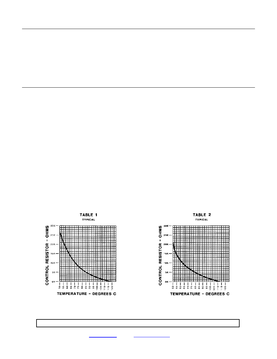
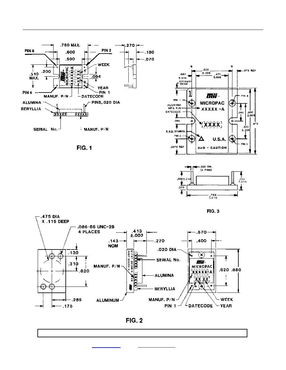
1. DC Heaters (Small Substrate) Use Table 1 for control resistor, and Figure 1 for dimensions.
2. DC Heaters (Large Substrate) Use Table 2 for control resistor, and Figure 3 for dimensions.
3. AC Heaters (Large Substrate) Use Table 2 for control resistor, and Figure 3 for dimensions.
4. Maximum temperature variation for current change from 5% over quiescent to 95% of turn-on current.
5. Maximum temperature variation over operating voltage range when ambient temperature is constant and the supply
current is between 5% over quiescent and 95% of turn-on current.
6. Maximum temperature with any value of control resistor, including 0 ohms.
7. All True hermetically sealed (solder welded) heater modules are leak tested to meet MIL-PRF-38534, Method 1014,
Test Conditions A & C, with a maximum lead rate of 1 X 10
-7
atm-cc/sec, and all hermetically sealed (epoxy) heaters
have a maximum leak rate of 1 X 10
-6
atm-cc/sec.
8. Optimum heat transfer is obtained by using a thermal joint compound such as Dow Corning 340 on the mounting
surface.
9. Operation is possible over +100°C, but electrical performance is not guaranteed. Input current decays to 20mA max
at +120°C without damage to the heater module.
10. All Mii DC heaters are protected against reverse voltage up to 50 V.
11. The standard ceramic heater design has pins for interconnect. The standard Micropac part number with or without
the A suffix will have pins & Micropac can supply the heater without pins and with pad metalization designed for wire
bonding. The version without pins will have a B suffix to the standard Micropac part number.
12. Maximum power rating for control resistor is 1/8 watts. Precise resistor values should be determined by measuring
the surface temperature.
13. The heater is operational from 24 to 32 VDC, however for optimum performance 28 VDC is recommended.

Micropac Industries cannot assume any responsibility for any circuits shown or represent that they are free from patent infringement.
Micropac reserves the right to make changes at any time in order to improve design and to supply the best product possible.
MICROPAC INDUSTRIES, INC. HYBRID MICROELECTRONICS PRODUCTS DIVISION
· 905 E. Walnut St., Garland, TX 75040 · (972) 272-3571 · Fax (972) 494-2281
www.micropac.com
E-MAIL:
hybridsales@micropac.com
12/13/01
3
True Hermetically Sealed
Proportionally Controlled Heater Hybrids
D.C. True Hermetic Seal
51974
28V / 28W
52005
20.5V / 15W
52027
28V / 40W
52086
18V / 15W
52087
28V / 15W
52088
32V / 30W
D. C. Hermetic Seal
51933
28V / 28W
51948
20V / 4W
51949
28V / 21W
51951
20V / 20W
51952
28V / 40W
51960
15V / 20W
51961
24V / 8W
51966
30V / 6W
51969
15V / 4W
51970
15V / 7.5W
51971
15V / 20W
51985
20.5V / 15W
52012
40V / 40W
52013
28V / 11W
52029
15V / 15W
52041
15V / 28W
52066
28V / 15W
D. C. Hermetic Seal
(Large Substrate)
52048
52055
20V / 40W
28V / 50W
D. C. True Hermetic Seal
(Large Substrate)
52056
52070
28V /50W
28V / 40W
A. C. Hermetic Seal
52031
52057
115V / 28W
115V / 40W
A. C. True Hermetic Seal
52034
115V / 28W
Pin No.
Function
1
+ Voltage
2
- Voltage (Return Voltage)
3
Control
4
Control
Micropac Industries cannot assume any responsibility for any circuits shown or represent that they are free from patent infringement.
Micropac reserves the right to make changes at any time in order to improve design and to supply the best product possible.
MICROPAC INDUSTRIES, INC. HYBRID MICROELECTRONICS PRODUCTS DIVISION
· 905 E. Walnut St., Garland, TX 75040 · (972) 272-3571 · Fax (972) 494-2281
www.micropac.com
E-MAIL:
hybridsales@micropac.com
12/13/01
4
True Hermetically Sealed
Proportionally Controlled Heater Hybrids
Micropac Industries cannot assume any responsibility for any circuits shown or represent that they are free from patent infringement.
Micropac reserves the right to make changes at any time in order to improve design and to supply the best product possible.
MICROPAC INDUSTRIES, INC. HYBRID MICROELECTRONICS PRODUCTS DIVISION
· 905 E. Walnut St., Garland, TX 75040 · (972) 272-3571 · Fax (972) 494-2281
www.micropac.com
E-MAIL:
hybridsales@micropac.com
12/13/01
5
True Hermetically Sealed
Proportionally Controlled Heater Hybrids
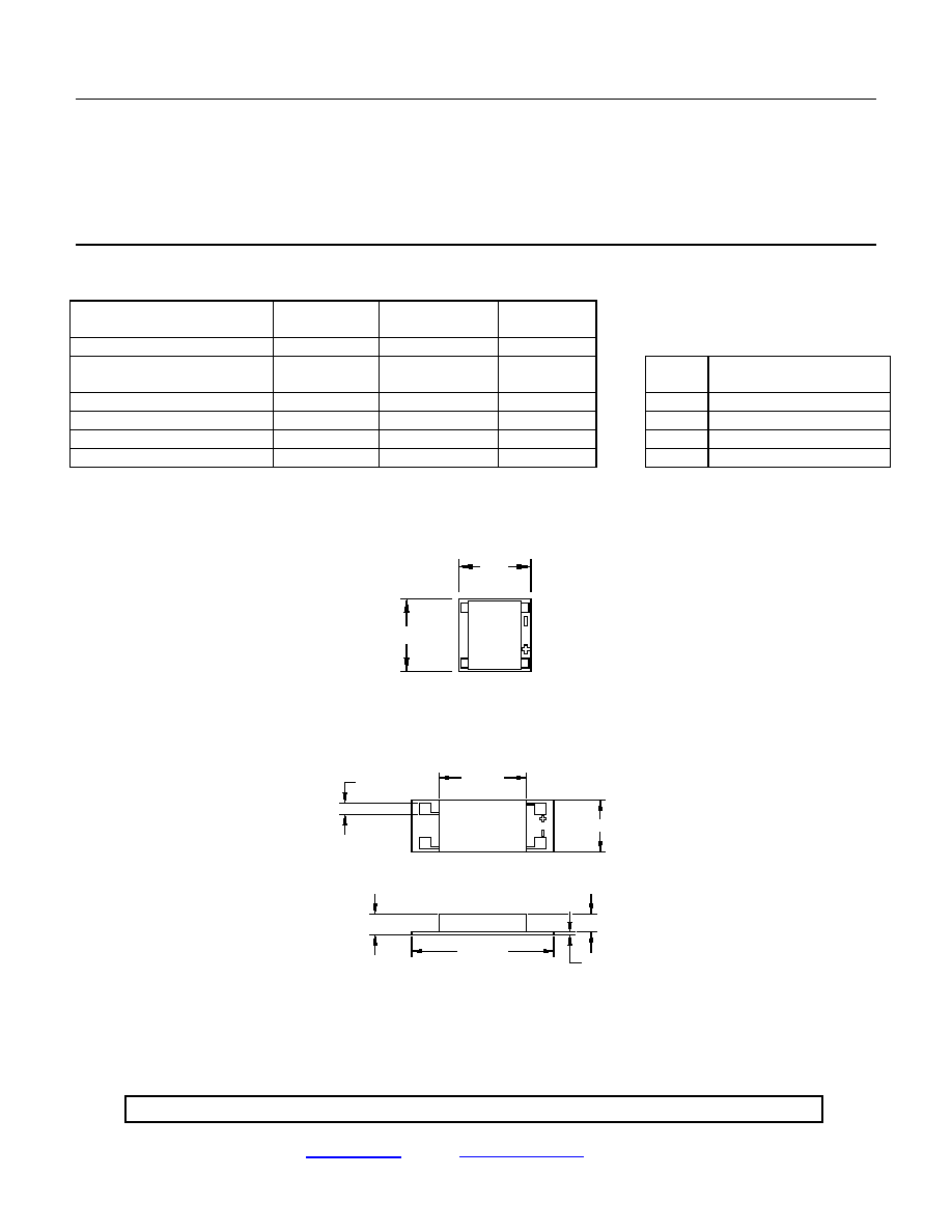
Proportionally Controlled Micro DC Heater Hybrid
Micropac Industries, Inc., a supplier of state of the art integrated hybrid circuits, introduces a new Micro D heater
offering a low cost alternative to standard heaters, as a temperature stabilization method for a variety of
applications including Saw Filters, VCOs and YIG Oscillators. These heaters are programmable via a single
external resistor. Dimensions are .200 by .200 (Fig. 1) to 1.4 by .5 inches (Fig. 2). Power ratings are from 1.5
watts to 28 watts. For more information on custom heater hybrids, please contract your local Mii representative or
call Mii directly.
Electrical Characteristics
52250-2
Fig. 1
52228-B
Fig. 2
Operating Voltage
15.0
24.0
VDC
Voltage Limits
13.0
17.0
22.0
28.0
VDC min.
VDC max.
Pin
Function
Operating Current
10 to 100
15 to 200
mA
1
+VDC
Turn On Current
to 100
to 200
mA
2
-VDC
Isolation (Pin to Backside)
1000
1000
VDC
3
Control
Power Dissipation
1.5
4.8
watts
4
Control
Vcc
.200
.200
GND
RESIS
T
OR
CONT
ROL
.110 SQ.
(4 PLACES)
.865
MAX.
.510 MAX.
.175 +.015
.165 MAX.
-
1.40
MAX.
.025
NOM.
Fig. 1
Fig. 2