 | –≠–ª–µ–∫—Ç—Ä–æ–Ω–Ω—ã–π –∫–æ–º–ø–æ–Ω–µ–Ω—Ç: 66024-003 | –°–∫–∞—á–∞—Ç—å:  PDF PDF  ZIP ZIP |
MICROPAC INDUSTRIES, INC.
OPTOELECTRONIC PRODUCTS DIVISION ∑ 725 E. Walnut St., Garland, TX 75040 ∑ (972) 272-3571 ∑ Fax (972) 487-6918
www.micropac.com
E-MAIL:
optosales@micropac.com
3 - 28
66024
4N55 DUAL CHANNEL, HERMETICALLY
SEALED OPTOCOUPLER
Mii
OPTOELECTRONIC PRODUCTS
DIVISION
Features:
∑ DSCC Approved 5962-8767901EX
∑ 1500 Vdc isolation test voltage
∑ TTL and CMOS compatible
∑ 2MHz bandwidth typical
∑
Faraday shield to provide high
common mode rejection
Applications:
∑ Military
and
space
∑ Voltage level shifting
∑ Isolated receiver input
∑ Communication
systems
∑ Medical
systems
DESCRIPTION
The 66024 optocoupler contains two completely isolated optocouplers in a hermetically sealed dual inline package. Each
channel provides high switching speeds while providing high isolation (1500V min) over the full military temperature range
(-55∞ to +125∞C). The 66024 is available in standard and MIL-PRF-38534 screened versions or tested to customer
specifications.
ABSOLUTE MAXIMUM RATINGS
Storage Temperature............................................................................................................................................ -65∞C to +150∞C
Operating Free-Air Temperature Range .............................................................................................................. -55∞C to +125∞C
Lead Solder Temperature..........................................................................................260∞C for 10s (1.6mm below seating plane)
Peak Forward Input Current ......................................................................................................................... 40mA (1ms duration)
Average Forward Input Current .............................................................................................................................................20mA
Input Power Dissipation ........................................................................................................................................................40mW
Reverse Input Voltage (each channel) .......................................................................................................................................5V
Supply voltage - V
CC
(each channel) ........................................................................................................................................20V
Output Current - I
O
(each channel) .......................................................................................................................................20mA
Output Power Dissipation (each channel)..(derate linearly at a rate of 1.4mW/∞C above 100
∞
C .......................................50mW
Output Voltage - V
O
(each channel) .........................................................................................................................................20V
Base Current (each channel)....................................................................................................................................................5mA
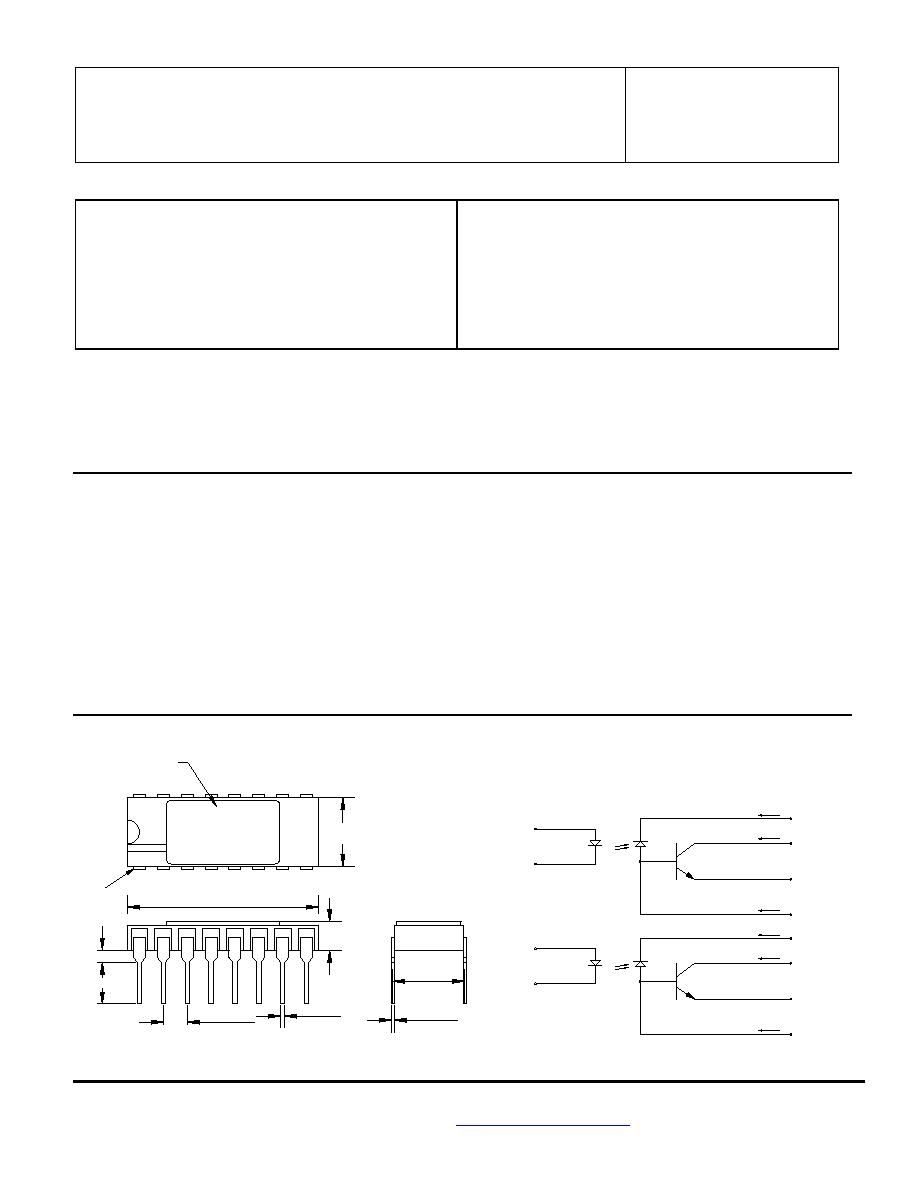
Package Dimensions Schematic Diagram
.790 [20.06]
.820 [20.83]
Mii 4N55
0.150 [3.81]
PIN 1
XXXX
ALL DIMENSIONS ARE IN INCHES [MILLIMETERS]
.290 [7.37]
.310 [7.87]
0.170 [4.32
MAX]
.320 [8.13]
MAX
DATE CODE
0.050 [1.27]
8
7
4
3
11 Vcc2
A
K
IB
I0
VB2
12
V02
GND2
10
9
K
A
15 Vcc1
IB
Icc
I0
13 GND1
VB1
16
V01
14
1CC
.007 [0.18]
0.13 [0.33]
0.20 [0.51]
MAX
.090 [2.29]
.110 [2.79]
MICROPAC INDUSTRIES, INC.
OPTOELECTRONIC PRODUCTS DIVISION ∑ 725 E. Walnut St., Garland, TX 75040 ∑ (972) 272-3571 ∑ Fax (972) 487-6918
www.micropac.com
E-MAIL:
optosales@micropac.com
3 - 29
66024
4N55 DUAL CHANNEL, HERMETICALLY SEALED OPTOCOUPLER
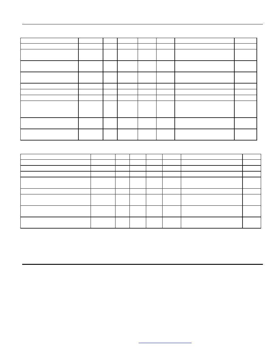
ELECTRICAL CHARACTERISTICS
T
a
= -55
∞
C to 125
∞
C unless otherwise specified.
PARAMETER
SYMBOL
MIN
TYP
MAX
UNITS
TEST CONDITIONS
NOTE
Current Transfer Ratio
CTR
9
20
%
I
F
= 16mA, V
O
= 0.4V , V
CC
= 4.5V
1, 2
Output Leakage Current
I
OH1
70
250
µ
A
I
F
= 250
µ
A, V
CC
= V
O
= 18V
I
F
(other channel) = 20mA
1
Logic High Output Current
I
OH
20
100
µ
A
I
F
= 0, V
CC
= V
O
= 18V
I
F
(other channel) = 20mA
1
High Level Output Current
I
CCH
0.2
10
µ
A
I
F
= 0, V
CC
= 18V
I
F
(other channel) = 20mA
1
Low Level Supply Current
I
CCL
35
200
µ
A
I
F1
= I
F2
= 20mA, V
CC
= 18V
1
Input Forward Voltage
V
F
1.5
1.8
V
I
F
= 20mA
1
Input Reverse Breakdown Voltage
BV
R
3
V
I
R
= 10µA
1
Input-Output Insulation Leakage
Current
I
I--O
1.0
µA
V
I--0
= 1500Vdc,
Relative Humidity = 45%
t
A
= 25∞C, t = 5s
3
Propagation Delay Time To High
Output Level
t
PLH
2
6
µ
s
I
F
= 16mA, V
CC
= 5V, R
L
= 8.2k
C
L
= 50pF
1
Propagation Delay Time To Low
Output Level
t
PHL
0.4
2
µ
s
I
F
= 16mA, V
CC
= 5V, R
L
= 8.2k
C
L
= 50pF
1
TYPICAL CHARACTERISTICS
T
a
= 25
∞
C, V
CC
= 5V Each Channel
PARAMETER
SYMBOL
MIN
TYP
MAX
UNITS
TEST CONDITIONS
NOTE
Input Capacitance
C
IN
120
pF
V
F
= 0, f = MHz
1
Capacitance (Input-Output)
C
I-O
1.5
pF
f = 1MHz, V
F
= 0
1, 4
Capacitance (Input-Input)
C
I-I
0.55
pF
f = 1MHz
Input Diode Temperature Coefficient
v
F
T
A
-1.9
mV/
∞
C
I
F
= 18mA
1
Resistance (Input-Output)
R
I-0
10
12
V
I--O
= 500Vdc
1
Input-Input Insulation Leakage Current
I
I-I
1
pA
Relative Humidity = 45%
V
I-I
= 500Vdc, t = 5s
3
Common Mode Transient immunity at High
Output Level
CM
H
500
1000
V/
µ
s
V
CM
= 10V
P-P
, R
L
= 8.2k
,
I
F
= 0mA
1, 5
Common Mode Transient Immunity at Low
Output Level
CM
L
500
1000
V/
µ
s
V
CM
= 10V
P-P
, R
L
= 8.2k
,
I
F
= 16mA
1, 6
NOTES:
1. Each
channel.
2.
CURRENT TRANSFER RATIO is defined as the ratio of output collector current, I
O
, to the forward LED input current, I
F
, times 100%.
3.
Measured between each input pair shorted together.
4.
Measured between input pins shorted together and the output pins for that channel shorted together.
5. CM
H
is the maximum tolerable common mode transient to assure that the output will remain in a high logic state (ie. V
O
>
@.0V).
6. CM
L
is the maximum tolerable common mode transient to assure that the output will remain in a low logic state (ie. V
O
<
0.8V).

MICROPAC INDUSTRIES, INC.
OPTOELECTRONIC PRODUCTS DIVISION ∑ 725 E. Walnut St., Garland, TX 75040 ∑ (972) 272-3571 ∑ Fax (972) 487-6918
www.micropac.com
E-MAIL:
optosales@micropac.com
3 - 30
66024
4N55 DUAL CHANNEL, HERMETICALLY SEALED OPTOCOUPLER
RECOMMENDED OPERATING CONDITIONS:
PARAMETER
SYMBOL
MIN
MAX
UNITS
Input Current, Low Level
I
FL
0
2
µ
A
Supply Voltage
V
CC
2.0
18
V
SELECTION GUIDE
PART NUMBER
PART DESCRIPTION
66024-000
Dual Channel Optocoupler with 100% device screening
66024-001
DSCC Dwg 5962-8767901EX Dual Channel Optocoupler
66024-002
Dual Channel, Optocoupler tested over full military temperature range (-55
∞
to +125
∞
C)
66024-003
Dual Channel, commercial (0
∞
to 70
∞
C)