
MICROPAC INDUSTRIES, INC.
OPTOELECTRONIC PRODUCTS DIVISION ∑ 725 E.Walnut Str., Garland, TX 75040 ∑ (972)272-3571 ∑ Fax (972)487-6918
www.micropac.com
E-MAIL: OPTOSALES @ MICROPAC.COM
2 - 2
67025
4N41-SEVEN SEGMENT HERMETICALLY SEALED DISPLAY
Mii
OPTOELECTRONIC PRODUCTS
DIVISION
Features:
∑ Hermetically
Sealed
∑ Left
Hand
Decimal
∑ TTL
Compatible
∑ High Luminous Intensity
∑ Large Character Height
Applications:
∑ High reliability systems
∑ Instrumentation
panels
∑ Communication
equipment
∑ Medical
equipment
DESCRIPTION
The 67025 (4N41) is a hermetically sealed seven segment display. The high luminous intensity and large character height
make the 67025 ideal for most applications. This high reliability display is available in standard and screened versions.
ABSOLUTE MAXIMUM RATINGS
Storage Temperature..........................................................................................................................................-65∞C to +125∞C
Operating Free-Air Temperature Range ............................................................................................................-55∞C to +100∞C
Lead Solder Temperature (1/16" [1.6mm] below seating plane for 10s) ........................................................................... 260∞C
Reverse Voltage at 25∞C Free-Air Temperature
Each Segment .................................................................................................................................................................. 6V
Decimal Point..................................................................................................................................................................... 3V
Peak Forward Current at (or below) 70∞C Free-Air Temperature (derate linearly to 100∞C at the rate of 6.7mA/∞C)
Each Segment or Decimal Point ...............................................................................................................................200mA
Average Forward Current at (or below) 70∞C Free-Air Temperature (derate linearly to 100∞C at the rate of 1mA/∞C for each
segment or 8mA/∞C for total device)
Each Segment or Decimal Point ..................................................................................................................................30mA
Package Dimensions Schematic Diagram
P IN 1
1
2
3
4
5
6
7
8
9
1 0
1 1
1 2
1 3
1 4
A N O D E S
E ,F ,G ,D P
A N O D E S
A ,B ,
A N O D E S
C ,D
D P
A
F
B
C
D
E
G
N C
N C
N C
N C -N O IN T E R N A L C O N N E C T IO N
0 .1 6 2 [4 .1 1 ]
0 .1 7 6 [4 .5 0 0 ]
1 0 ∞
S E A T IN G P L A N E
0 .7 6 0 [1 9 .3 1 ]
0 .7 4 0 [1 8 .7 9 ]
A
G
D
E
F
C
B
D .P .
A L L P IN S
1 4
1 3
1 2
1 1
1 0
9
8
7
6
5
4
2
3
1
0 .4 1 0 [1 0 .4 2 ]
0 .3 9 0 [9 .9 0 ]
0 .3 0 0 [7 .6 2 ]
A L L P IN S
0 .2 6 0 [6 .6 0 ]
0 .0 1 0 [0 .3 1 0 ]
0 .2 2 0
[5 .6 ]
0 .1 8 0
[4 .6 ]
0 .1 2 7 [3 .2 3 ]
0 .1 2 7 [3 .2 3 ]
0 .0 8 7 [2 .2 0 ]
0 .1 5 0 [3 .8 1 ]
0 .0 4 5 [1 .1 4 ] M IN
0 .0 2 2 [0 .5 6 ]
0 .0 1 8 [0 .4 5 7 ]
0 .0 1 2 [0 .3 0 ]
0 .0 0 8 [0 .3 0 5 ]
A L L P IN S
0 .0 7 5 [1 .9 0 ] M A X
0 .0 7 5 [1 .9 0 ] M A X
0 .0 8 5 [2 .1 6 ] M A X
0 .1 0 0 [2 .5 4 ] T .P .
1 2 P L A C E S
(S E E N O T E C .)
0 .0 8 5 [2 .1 5 ] M A X
NOTES:
a. All linear dimensions are in millimeters and parenthetically in inches.
b. Centerlines of character segments and decimal points are shown as dashed lines. Associated dimensions are nominal.
c. The true-position pin spacing is 2.54mm (0.10") between centerlines. Each centerline is located within 0.26mm (0.010") of it's true longitudinal
position relative to pins 4 and 11.
MICROPAC INDUSTRIES, INC.
OPTOELECTRONIC PRODUCTS DIVISION ∑ 725 E.Walnut Str., Garland, TX 75040 ∑ (972)272-3571 ∑ Fax (972)487-6918
www.micropac.com
E-MAIL: OPTOSALES @ MICROPAC.COM
2 - 3
67025
4N41-SEVEN SEGMENT HERMETICALLY SEALED DISPLAY
ELECTRICAL CHARACTERISTICS
T
A
= 25
∞C unless otherwise specified.
PARAMETER
SYMBOL
MIN
TYP
MAX
UNITS
TEST CONDITIONS
Luminous Intensity
1
I
V
200
700
µcd
I
F
= 20mA
Wavelength at Peak Emission
P
640
660
680
nm
I
F
= 20mA
Spectral Bandwidth
20
nm
I
F
= 20mA
Static Forward Voltage
V
F
3
3.4
3.8
V
I
F
= 20mA
Average Temperature Coefficient of Static
Voltage
v
F
T
A
-2.7
mV/
∞
C
I
F
= 20mA, t
A
= 0
∞
C to 100
∞
C
Static Reverse Current
I
R
100
µ
A
V
R
= 6V
Anode-to-Cathode Capacitance
C
85
pF
V
R
= 0V, f = 1MHz
NOTES:
1.
Luminous intensity is measured with a light sensor and filter combination that approximates the CIE (International Commission on Illumination) eye-
response curve.
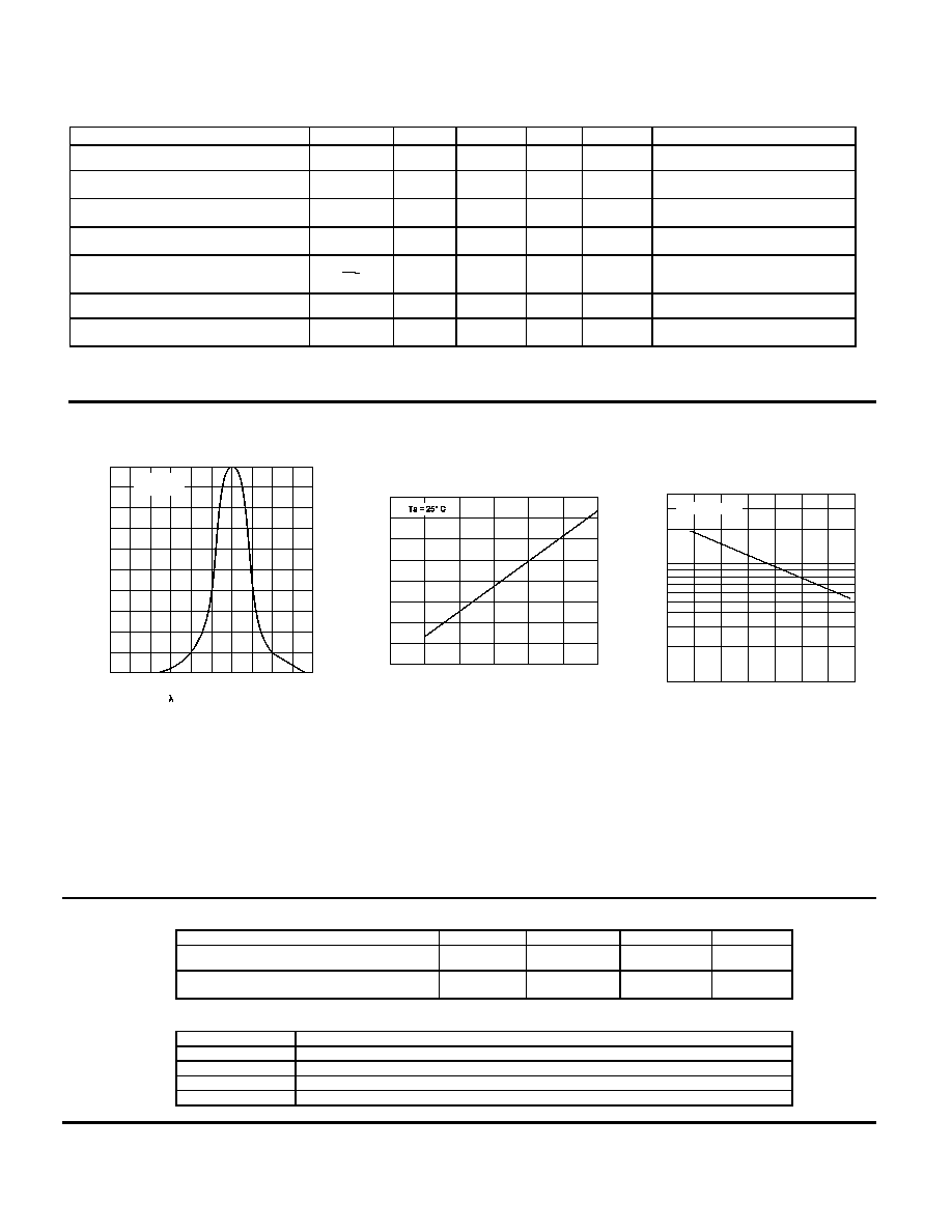
RELATIVE SPECTRAL CHARACTERISTICS
- Wavelength - nm
600
620
640
660
700
680
0
0.1
0.2
0.3
0.4
0.5
0.6
0.7
0.8
Lun
ino
u
s
I
n
t
ens
it
y Relat
i
ve
0.9
1.0
Ta = 25∞ C
I = 20 mA
F
FIGURE 1
RELATIVE LUMINOUS INTENSITY
vs
FORWARD CURRENT
I - FORWARD CURRENT - mA
0
5
10
15
25
20
0
0.2
0.4
0.6
0.8
1.0
1.2
1.4
1.6
F
to V
a
lue a
t
I =
20 mA
Luni
nous
Intens
ity
Relat
i
ve
F
30
FIGURE 3
RELATIVE LUMINOUS INTENSITY
vs
FREE-AIR TEMPERATURE
T - FREE AIR TEMPERATURE - ∞C
-75
-50
-25
0
50
25
0.1
0.2
to
V
a
lu
e
a
t
T
=
2
5
∞
C
Lu
ni
n
ous
I
n
t
e
ns
i
t
y
R
e
l
a
t
i
v
e
A
75
100
0.4
0.7
1
2
4
I = CONSTANT
F
FIGURE 2
RECOMMENDED OPERATING CONDITIONS:
PARAMETER
SYMBOL
MIN
MAX
UNITS
Forward Current
I
F
20
30
mA
Operating Temperature
T
A
-55
100
∞
C
SELECTION GUIDE
PART NUMBER
PART DESCRIPTION
67025-001
4N41 Mil-Temp only (-55
∞
to +100
∞
C)
67025-101
4N41 Mil-Temp (-55
∞
to +100
∞
C) with 100% screening.
67025-003
4N41 Commercial (0
∞
to
70
∞
C)
67025-004
4N41 Industrial-Temp only (-40
∞
to +85
∞
C)