ISO 9001 CERTIFIED
REV D 11/01/99
8700 E. Thomas Road
Scottsdale, AZ 85251
Tel: (480) 941-6300
Fax (480) 947-1503
1PMT5283
thru
1PMT5314
FEATURES:
∑
Surface-mount equivalent to 1N5283 thru 1N5314 series
∑
Popular Microsemi Powermite
Æ
surface-mount package
∑
Nominal current regulation from 0.22 and 4.70 mA
∑
Broad operating voltage
∑
Constructed with an Oxide Passivated All Diffused Die
∑
Full metallic bottom eliminates flux entrapment
∑
Integral Heat Sink Locking Tabs for excellent thermal dissipation and improved
current regulation
MAXIMUM RATINGS:
∑
Operating and Storage Temperature: -55
∞
C to +150
∞
C
∑
DC Power Dissipation: 600mW @ T
L
135
∞
C
∑
Power Derating: 40mW/
∞
C @ T
L
> 135
∞
C
∑
Peak operating voltage: 100 Volts
MECHANICAL CHARACTERISTICS
∑
Terminals: Leads tin plated
∑
Thermal resistance: 30
∞
C/W junction to Tab 1
∑
Polarity: Cathode indicated by a band
∑
Packaging: Tape and Reel (EIA Standard RS-481)
∑
Weight 0.016 gram
∑
Mounting position any way
PACKAGING
∑
Tape and Reel Standard 481
∑
7 inch Reel 3,000 Pieces
∑
13 inch Reel 12,000 Pieces
CURRENT REGULATOR DIODES
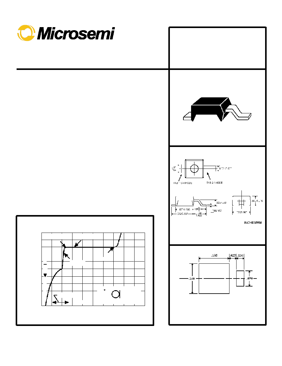
Anode
Cathode
POV
Z
K
@ V
K
VL @ IL
I
P
& Z
S
@V
Reverse
Forwar
Revers
Forward
-2.0 -1.0
0
20
40
60
80
90
100 120 140
V
AK
≠ ANODE CATHODE VOLTAGE (VOLTS)
TYPICAL CURRENT REGULATOR CHARACTERISTICS
Mounting Pad Dimensions in Inches
D0-216
All dimensions +/- .005 inches/0.127mm
5.0
1.0
2.0
3.0
4.0
-20
0
-80
-100
-40
-60

ISO 9001 CERTIFIED
REV D 11/01/99
REGULATOR
CURRENT
I
P
(mA)@ V
S
= 25V
PART
NUMBER
NOM
MIN
MAX
MINIMUM
DYNAMIC
IMPEDANCE
@V
S
=25v
Z
S
(M )
(NOTE 1)
MINIMUM
KNEE
IMPEDANCE
@V
K
= 6.0V
Z
K
(M )
(NOTE 2)
MAXIMUM
LIMITING
VOLTAGE
@I
L
= 0.8 I
P
(min)
V
L
(VOLTS)
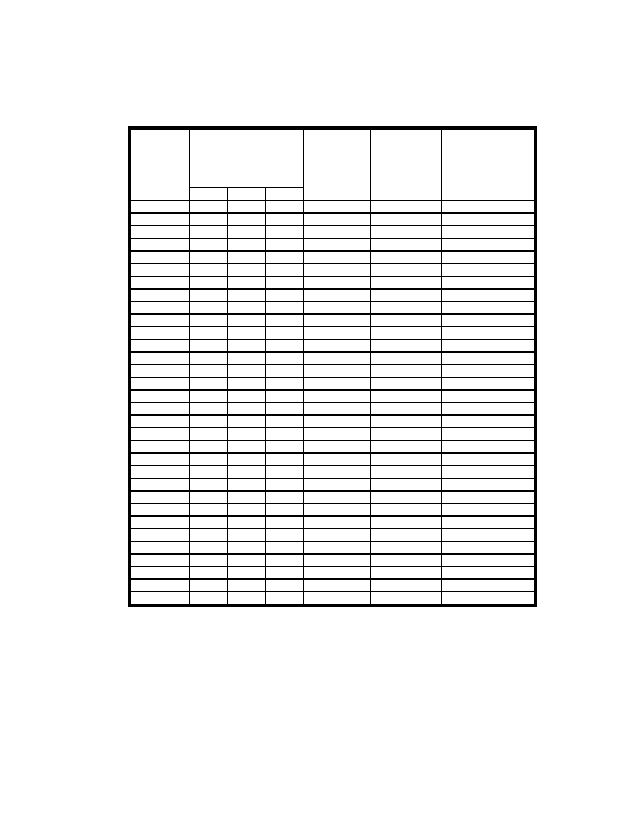
1PMT5283
0.22
0.198
0.242
25.0
2.75
1.00
1PMT5284
0.24
0.216
0.264
19.0
2.35
1.00
1PMT5285
0.27
0.243
0.297
14.0
1.95
1.00
1PMT5286
0.30
0.270
0.330
9.0
1.60
1.00
1PMT5287
0.33
0.297
0.363
6.6
1.35
1.00
1PMT5288
0.39
0.351
0.429
4.10
1.00
1.05
1PMT5289
0.43
0.387
0.473
3.30
0.870
1.05
1PMT5290
0.47
0.423
0.517
2.70
0.750
1.05
1PMT5291
0.56
0.504
0.616
1.90
0.560
1.10
1PMT5292
0.62
0.558
0.682
1.55
0.470
1.13
1PMT5293 0.68 0.612 0.748 1.35 0.400 1.15
1PMT5294
0.75
0.675
0.825
1.15
0.335
1.20
1PMT5295
0.82
0.738
0.902
1.00
0.290
1.25
1PMT5296
0.91
0.819
1.001
0.880
0.240
1.29
1PMT5297
1.00
0.900
1.100
0.800
0.205
1.35
1PMT5298
1.10
0.990
1.210
0.700
0.180
1.40
1PMT5299
1.20
1.06
1.32
0.640
0.155
1.45
1PMT5300
1.30
1.17
1.43
0.580
0.135
1.50
1PMT5301
1.40
1.26
1.54
O.540
0.115
1.55
1PMT5302
1.50
1.35
1.65
0.510
0.105
1.60
1PMT5303
1.60
1.44
1.76
0.475
0.092
1.65
1PMT5304
1.80
1.62
1.98
0.420
0.074
1.75
1PMT5305
2.00
1.80
2.20
0.395
0.061
1.85
1PMT5306
2.20
1.98
2.42
0.370
0.052
1.95
1PMT5307
2.40
2.16
2.64
0.345
0.044
2.00
1PMT5308
2.70
2.43
2.97
0.320
0.035
2.15
1PMT5309
3.00
2.70
3.30
0.300
0.029
2.25
1PMT5310
3.30
2.97
3.63
0.280
0.024
2.35
1PMT5311
3.60
3.24
3.96
0.265
0.020
2.50
1PMT5312
3.90
3.51
4.29
0.255
0.017
2.60
1PMT5313
4.30
3.87
4.73
0.245
0.014
2.75
1PMT5314
4.70
4.23
5.17
0.235
0.012
2.90
IPMT5283 thru IPMT5314
Electrical Characteristics @ TL=30∞C
NOTE 1
:
Z
S
is measured by superimposing a 90 Hz rms signal to 10% of V
S
on V
S
.
NOTE 2
:
Z
K
is derived by superimposing a 90 Hz rms signal to 10% of V
K
on V
K
.

ISO 9001 CERTIFIED
REV D 11/01/99
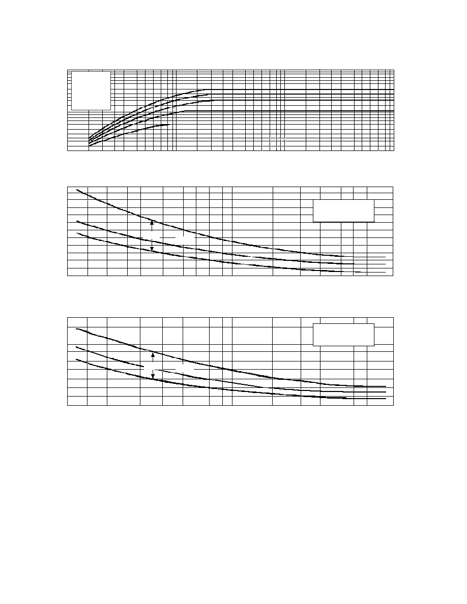
IPMT5283 thru IPMT5314
Typical Forward Characteristics
10
7
5
3
2
1
0.7
0.5
0.2
0.3
0.4
0.5
0.7
1.0
2.0
3.0
4.0
5.0
I
P
NOMINAL PINCH-OFF CURRENT (mA)
0.7
0.6
0.5
0.4
0.3
0.2
0.1
0
-0.1
-0.2
-0.3
1.0
0.8
0.6
0.4
0.2
0
-0.2
-0.4
-0.6
-0.8
0.2
0.3
0.4
0.5
0.7
1.0
2.0
3.0
4.0
5.0
I
P
NOMINAL PINCH-OFF CURRENT (mA)
I
D
FORWARD DIODE CURRENT (mA)
IS
- TEMPERATURE
COEFFICIENT (%/C)
IS
- TEMPERATURE
COEFFICIENT (%/C)
T
J
= 25
∞
C
V
SM
= 100V
(DATA
OBTAINED
FROM PULSE
TESTING)
T
J
= +25
∞
C to +150
∞
C
V
AK
= 25V
ƒ
I
P
=
IS
I
P(Nom)
ƒ
T
J
/100
T
J
= -55
∞
C to +25
∞
C
V
AK
= 25V
ƒ
I
P
=
IS
I
P(Nom)
ƒ
T
J
/100
Range
Range
Typica
Typical
1PMT5313
1PMT5309
1PMT5305
1PMT5298
1PMT5290
0.1
0.2
0.3
0.5
0.7
1.0
2.0
3.0
5.0
7.0 10.0
20
30
50
70 100
V
AK
ANODE- CATHODE VOLTAGE (VOLTS)
SYMBOLS AND DEFINITIONS
I
D
Diode Current
I
L
Limiting Current 80% of I
P
minimum used to determine Limiting Voltage, V
L
IS
Current Temperature Coefficient.
V
AK
anode to cathode Voltage
I
p
Pinch-off Current: Regulator current at specified Test Voltage, V
S
. I
P
is some times identified as I
S
POV
Peak Operating Voltage: Maximum voltage to be applied to the device.
V
K
Knee Impedance test voltage: Specified voltage used to establish Knee Impedance
V
L
Limiting Voltage: Measured at I
L
, V
L
, together with Knee ac Impedance, Z
K
, indicates the Knee characteristic of the device
V
S
TEST VOLTAGE: Voltage at which I
P
and Z
S
are specified
Z
K
Knee ac impedance at Test Voltage: To test Z
K
a 90Hz signal V
K
with rms value equal to 10% of test voltage V
K
is superimposed on V
K
:
Z
K
= V
K
/i
K
where i
K
is the resultant ac current due to v
K
. To provide the most constant current from the diode, Z
K
should be as high as
possible, therefore, a minimum value of Z
K
is specified.
Z
S
AC Impedance at Test Voltage: Specified as a minimum value. To test for Z
S
, a 90 Hz signal V
S
with rms value equal to 10% of test
voltage, V
S
is superimposed on V
S
: Z
S
= v
S
/i
S
where i
S
is the current due to v
S
.
Temperature Coefficient
Temperature Coefficient


