Silicon 2 Watt Zener Diode
Microsemi
Scottsdale Division
8700 E. Thomas Rd. PO Box 1390, Scottsdale, AZ 85252 USA, (480) 941-6300, Fax: (480) 947-1503
Page 1
Copyright
2003
7-12-2003 REV 0
W
W
W
.
Mi
c
r
o
s
e
m
i
.
C
O
M
S C O T T S D A L E D I V I S I O N
2EZ3.6D5 thru 2EZ200D5
2EZ3.6D5 thr
u
2EZ200
D5
DESCRIPTION
APPEARANCE
The 2EZ3.6D5 thru 2EZ200D5 series of axial-leaded 2.0 watt Zeners
provides voltage regulation selections with 5% tolerances from 3.6 to 200
volts in a DO-41 plastic package size. Other Zener voltage tolerances are
also available by changing the suffix number to the tolerance desired such
as 1 and 2 for tighter tolerances or 10 for wider tolerance. These plastic
encapsulated Zeners have moisture classification of Level 1 with no dry
pack required and are also available in various military equivalent
screening levels by adding a prefix identifier as also described in the
Features section. They may be operated at high maximum dc currents or
full power rating with adequate heat. Microsemi also offers numerous other
Zener products to meet higher and lower power applications.
DO-41 or
DO-204AL
(Plastic)
IMPORTANT: For the most current data, consult MICROSEMI's website:
http://www.microsemi.com
FEATURES
APPLICATIONS / BENEFITS
�
Zener voltage available 3.6 V to 200 V
�
Standard voltage tolerances are plus/minus 5%
with a 5 suffix and 10 % with 10 suffix identification
� Tight tolerances available in plus or minus 2% or
1% with 2 or 1 suffix respectively
�
Options for screening in accordance with MIL-
PRF-19500 for JAN, JANTX, JANTXV, and JANS
are available by adding MQ, MX, MV, or MSP
prefixes respectively to part numbers.
�
Surface mount equivalents available as
SMBJ2EZ3.6D5 to SMBJ2EZ200D5 in the DO-
214AA package, or SMBG2EZ3.6D5 to
SMBG200D5 in the DO-215AA package
� Regulates voltage over a broad operating current and
temperature range
� Wide selection from 3.6 to 200 V
� Flexible axial-lead mounting terminals
� Nonsensitive to ESD per MIL-STD-750 Method 1020
� Withstands surge stresses
� High specified maximum current (I
ZM
) when
adequately heat sunk
� Moisture classification is Level 1 per IPC/JEDEC
J-STD-020B with no dry pack required
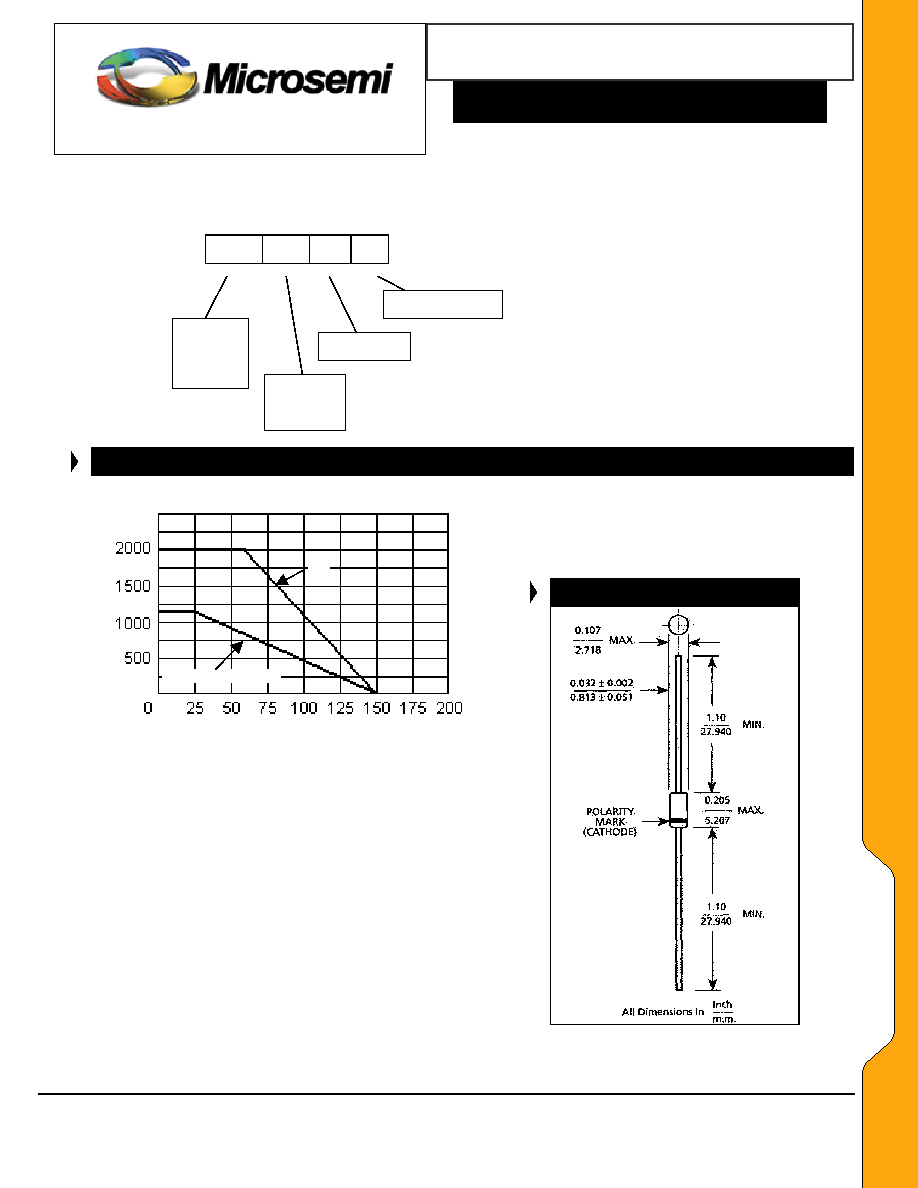
MAXIMUM RATINGS
MECHANICAL AND PACKAGING
�
Power dissipation at 25
�
C: 3.0 watts (also see
derating in Figure 1).
�
Operating and Storage temperature: -65
�
C to
+150
�
C
�
Thermal Resistance: 45
�
C/W junction to lead at
3/8 (10 mm) lead length from body, or 105
�
C/W
junction to ambient when mounted on FR4 PC
board (1oz Cu) with 4 mm
2
copper pads and track
width 1 mm, length 25 mm
�
Steady-State Power: 2 watts at T
L
< 60
o
C 3/8 inch
(10 mm) from body, or 1.19 watts at T
A
= 25
�
C
when mounted on FR4 PC described for thermal
resistance (also see Figure 1)
�
Forward voltage @200 mA: 1.2 volts (maximum)
�
Solder Temperatures: 260
�
C for 10 s (max)
�
CASE: Void-free transfer molded thermosetting
epoxy body meeting UL94V-0
�
TERMINALS: Leads, tin-lead plated solderable per
MIL-STD-750, method 2026
�
POLARITY: Cathode indicated by band where diode
is to be operated with the banded end positive with
respect to the opposite end for Zener regulation.
�
MARKING: Part number
�
TAPE & REEL option: Standard per EIA-296 (add
"TR" suffix to part number)
�
WEIGHT: 0.4 grams
�
See package dimensions on last page

Silicon 2 Watt Zener Diode
S C O T T S D A L E D I V I S I O N
2EZ3.6D5 thru 2EZ200D5
W
W
W
.
Mi
c
r
o
s
e
m
i
.
C
O
M
2EZ3.6D5 thr
u
2EZ200
D5
ELECTRICAL CHARACTERISTICS @ 25
o
C
NOMINAL ZENER
VOLTAGE
(Note 2)
MAXIMUM ZENER IMPEDANCE
(Note 3)
MAXIMUM
REVERSE
CURRENT
MAXIMUM
RATED
ZENER
CURRENT
@ 100
o
C
MAXIMUM
SURGE
CURRENT
(Note 4)
V
Z
@ I
Z
Z
ZT
@ I
ZT
Z
ZK
@ I
ZK
I
R
@ V
R
I
ZM
I
ZSM
MICRO
TYPE
NUMBER
(Note 1)
VOLTS mA OHMS OHMS mA
�A
VOLTS mA
A
2EZ3.6D5
2EZ3.9D5
2EZ4.3D5
2EZ4.7D5
2EZ5.1D5
3.6
3.9
4.3
4.7
5.1
139
128
116
106
98
5.0
5.0
4.5
4.5
3.5
400
400
400
550
600
1.0
1.0
1.0
1.0
1.0
80
30
20
5.0
5.0
1.0
1.0
1.0
1.0
1.0
504
468
434
386
356
4.6
4.4
4.1
3.3
3.5
2EZ5.6D5
2EZ6.2D5
2EZ6.8D5
2EZ7.5D5
2EZ8.2D5
5.6
6.2
6.8
7.5
8.2
89.5
80.5
73.5
66.5
61
2.5
1.5
2.0
2.0
2.3
500
700
700
700
700
1.0
1.0
1.0
0.5
0.5
5.0
5.0
5.0
5.0
5.0
2.0
3.0
4.0
5.0
6.0
324
292
266
242
220
3.3
3.1
2.9
2.66
2.44
2EZ9.1D5
2EZ10D5
2EZ11D5
2EZ12D5
2EZ13D5
9.1
10
11
12
13
55
50
45.5
41.5
38.5
2.5
3.5
4.0
4.5
5.0
700
700
700
700
700
0.5
0.25
0.25
0.25
0.25
3.0
3.0
1.0
1.0
0.5
7.0
7.6
8.4
9.1
9.9
200
182
166
152
138
2.2
2.0
1.82
1.66
1.54
2EZ14D5
2EZ15D5
2EZ16D5
2EZ17D5
2EZ18D5
14
15
16
17
18
35.7
33.4
31.2
29.4
27.8
5.5
7.0
8.0
9.0
10
700
700
700
750
750
0.25
0.25
0.25
0.25
0.25
0.5
0.5
0.5
0.5
0.5
10.6
11.4
12.2
13.0
13.7
130
122
114
107
100
1.43
1.33
1.25
1.18
1.11
2EZ19D5
2EZ20D5
2EZ22D5
2EZ24D5
2EZ27D5
19
20
22
24
27
26.3
25
22.8
20.8
18.5
11
11
12
13
18
750
750
750
750
750
0.25
0.25
0.25
0.25
0.25
0.5
0.5
0.5
0.5
0.5
14.4
15.2
16.7
18.2
20.6
95
90
82
76
68
1.05
1.0
0.91
0.83
0.74
2EZ30D5
2EZ33D5
2EZ36D5
2EZ39D5
2EZ43D5
30
33
36
39
43
16.6
15.1
13.9
12.8
11.6
20
23
25
30
35
1000
1000
1000
1000
1500
0.25
0.25
0.25
0.25
0.25
0.5
0.5
0.5
0.5
0.5
22.5
25.1
27.4
29.7
32.7
60
55
50
47
43
0.67
0.61
0.56
0.51
0.45
2EZ47D5
2EZ51D5
2EZ56D5
2EZ62D5
2EZ68D5
47
51
56
62
68
10.6
9.8
9.0
8.1
7.4
40
48
55
60
75
1500
1500
2000
2000
2000
0.25
0.25
0.25
0.25
0.25
0.5
0.5
0.5
0.5
0.5
35.8
38.8
42.6
47.1
51.7
39
36
32
29
27
0.42
0.39
0.36
0.32
0.29
2EZ75D5
2EZ82D5
2EZ91D5
2EZ100D5
2EZ110D5
75
82
91
100
110
6.7
6.1
5.5
5.0
4.5
90
100
125
175
250
2000
3000
3000
3000
4000
0.25
0.25
0.25
0.25
0.25
0.5
0.5
0.5
0.5
0.5
56
62.2
69.2
76.0
83.6
24
22
20
18
17
0.27
0.24
0.22
0.20
0.18
2EZ120D5
2EZ130D5
2EZ140D5
2EZ150D5
2EZ160D5
120
130
140
150
160
4.2
3.8
3.6
3.3
3.1
325
400
500
575
650
4500
5000
5500
6000
6500
0.25
0.25
0.25
0.25
0.25
0.5
0.5
0.5
0.5
0.5
91.2
98.8
106.4
114
121.6
15
14
13
12
11
0.16
0.15
0.14
0.13
0.12
2EZ170D5
2EZ180D5
2EZ190D5
2EZ200D5
170
180
190
200
2.9
2.8
2.6
2.5
675
725
825
900
7000
7000
8000
8000
0.25
0.25
0.25
0.25
0.5
0.5
0.5
0.5
130.4
136.8
144.8
152
11
10
10
9
0.12
0.11
0.10
0.10
NOTES: 1. Suffix 1 indicates +/-1% tolerance, suffix 2 indicates +/-2% tolerance, suffix 5 indicates +/-5% tolerance. Suffix 10 indicates +/-10%,
no suffix indicates +/-20%.
2. The
V
Z
is measured after allowing a 90 second stabilization period when mounted with a 3/8" minimum lead length from body.
Ambient temperature, T
A
= 25
o
C (+8
o
C/-2
o
C).
3.
The Zener impedance is derived from 60 cycle ac voltage resulting from an ac current having an rms value equal to 10%
of the dc Zener current (I
ZT
or I
ZK
) is superimposed on I
ZT
or I
ZK
.
4. Maximum Surge Current I
ZSM
is a non-recurrent maximum peak reverse surge with a pulse width of 8.3 ms.
Microsemi
Scottsdale Division
8700 E. Thomas Rd. PO Box 1390, Scottsdale, AZ 85252 USA, (480) 941-6300, Fax: (480) 947-1503
Page 2
Copyright
2003
7-12-2003 REV 0