 | –≠–ª–µ–∫—Ç—Ä–æ–Ω–Ω—ã–π –∫–æ–º–ø–æ–Ω–µ–Ω—Ç: FDS6612A | –°–∫–∞—á–∞—Ç—å:  PDF PDF  ZIP ZIP |
LXE1710 E
VALUATION
B
OARD
U
SER
G
UIDE
Microsemi
Linfinity Microelectronics Division
11861 Western Avenue, Garden Grove, CA. 92841, 714-898-8121, Fax: 714-893-2570
Page 1
Copyright
©
2000
Rev. 1.1, 2000-12-01
�
�
A M I C R O S E M I C O M P A N Y

LXE1710 E
VALUATION
B
OARD
U
SER
G
UIDE
Microsemi
Linfinity Microelectronics Division
11861 Western Avenue, Garden Grove, CA. 92841, 714-898-8121, Fax: 714-893-2570
Page 2
Copyright
©
2000
Rev. 1.1, 2000-12-01
I
NTRODUCING
LX1710/1711 A
UDIO
MAX
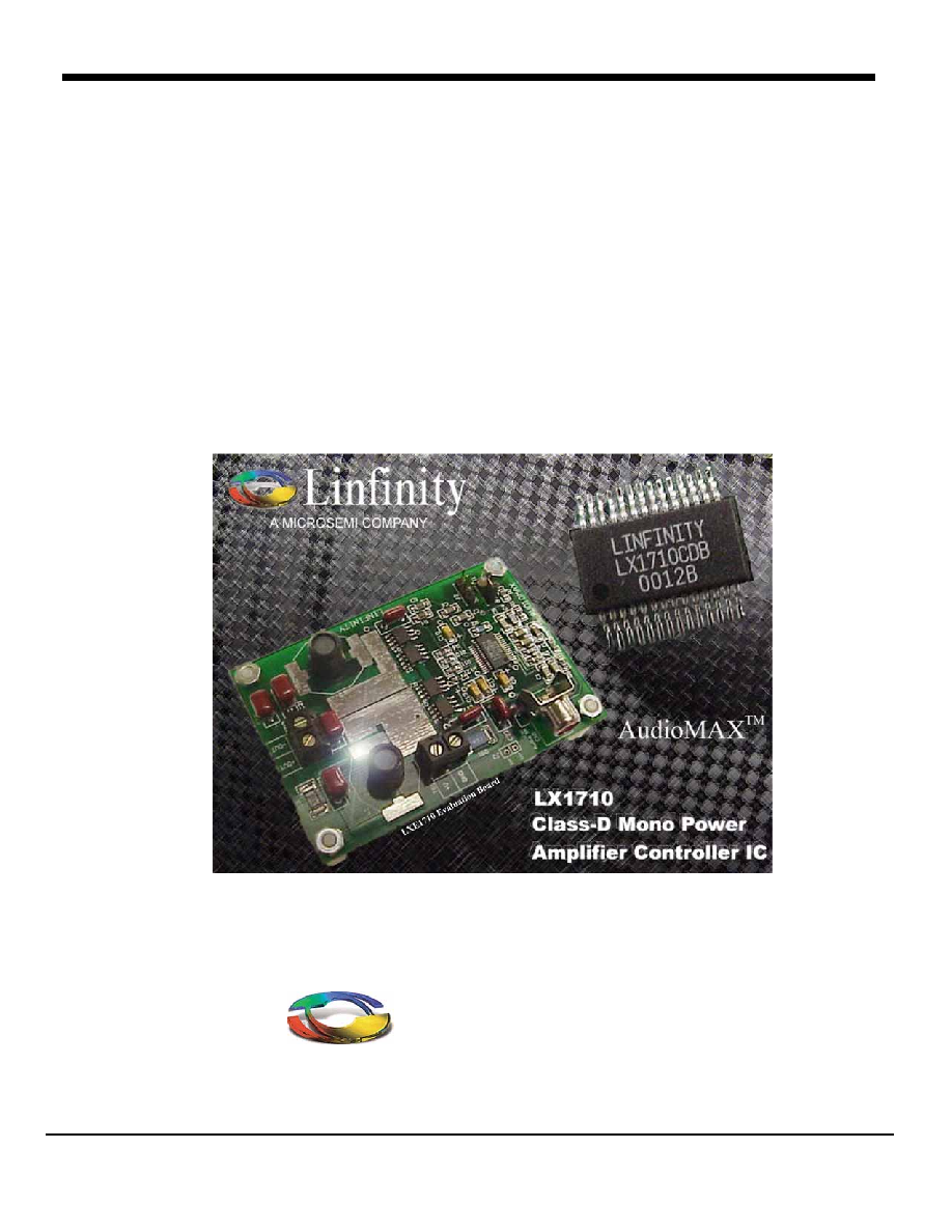
Thank you for your interest in the latest generation of AudioMAX products. The enclosed LXE1710 evaluation
board is a fully functional mono amplifier designed to demonstrate the "new and improved" Switching Class-D
Power Amplifier IC from Linfinity Microsemi. The LX1710/1711 is a completely new controller design with
superior performance over the LX1720 stereo controller IC. Key improvements include better SNR, lower noise
floor, and reduced THD therefore resulting in a much "quieter" and "cleaner" sounding amplifier.
The evaluation board has been configured with easy-to-use terminal block connections for power supply/battery hook
up and speaker connections. An RCA jack or separate audio +/- pins allow a quick interface to your audio source.
Jumpers are also provided to enable/disable the amplifier (Sleep control) and to turn off the audio input (Mute
control). With minimal setup, the user can be listening to the amplifier in a matter of a few minutes.
Both the LX1710 and LX1711 operate from a single supply voltage. The LXE1710 evaluation board can
�
�
!e
LX1711 can handle a higher supply voltage (7V to 25V) and provides greater than 50W continuous output power
! �
� " " � !
� " �
change frequency response for other load optimization.
Thank you again for your interest in the new "quieter", high efficiency Class-D Audio Amplifier from Linfinity
Microsemi. Please let us know what you think and stay tuned for future product releases to our AudioMAX family
of products.
Regards,
Linfinity Microsemi
http://www.linfinity.com
(714) 898-8121

LXE1710 E
VALUATION
B
OARD
U
SER
G
UIDE
Microsemi
Linfinity Microelectronics Division
11861 Western Avenue, Garden Grove, CA. 92841, 714-898-8121, Fax: 714-893-2570
Page 3
Copyright
©
2000
Rev. 1.1, 2000-12-01
T
ABLE OF
C
ONTENTS
LX1710 / 1710 AudioMAX Evaluation Board Features and Circuit Description
.............................4
Input
Compensation
Output Stage
Filter
Stage
Quick Start Guide
............................................................................................................................................5
Application Schematic
...................................................................................................................................6
Electrical Characteristics
..............................................................................................................................7
Performance Graphs
......................................................................................................................................8
Application Information
Filter Design Tradeoffs (1-Stage vs. 2-Stage).............................................................................................9
LC Filter Design...........................................................................................................................................9
MOSFET
Selection....................................................................................................................................10
Inductor
Selection......................................................................................................................................12
Capacitor
Selection ...................................................................................................................................13
Gate
Resistor ............................................................................................................................................14
Oscillator
Configuration .............................................................................................................................14
Multi Channel Requirements and Frequency Synchronization..................................................................14
PCB
Layout ...............................................................................................................................................15
Board Layout
..................................................................................................................................................16
Printed Circuit Board
...................................................................................................................................17
Bill of Materials
..............................................................................................................................................18

LXE1710 E
VALUATION
B
OARD
U
SER
G
UIDE
Microsemi
Linfinity Microelectronics Division
11861 Western Avenue, Garden Grove, CA. 92841, 714-898-8121, Fax: 714-893-2570
Page 4
Copyright
©
2000
Rev. 1.1, 2000-12-01
Part Number
Product
Description
LX1710CDB
AudioMAX High
Fidelity Controller IC
V
DD
= 7V to 15V, Switching Class-D Mono
Power Amplifier IC, 28-Pin SSOP Package.
LX1711CDB
AudioMAX High
Power Controller IC
V
DD
= 7V to 25V, Switching Class-D Mono
Power Amplifier IC, 28-Pin SSOP Package.
LXE1710
LX1710 AudioMAX
Evaluation Board
Fully Operational Mono Audio Amplifier.
LX1710/1711 A
UDIO
MAX E
VALUATION
B
OARD
F
EATURES AND
C
IRCUIT
D
ESCRIPTION
∑
Fully Assembled Mono Evaluation Board with
LX1710 Class-D Controller IC
∑
Improved SNR and Noise Floor Performance
∑
Output Power of 25W typical (LX1710, 15V
DD
,
�
∑
Output Power of 54W typical (LX1711, 25V
DD
,
�
∑
Supports Full Audio Bandwidth
∑
∑
Terminal Block Connectors for Supply
Voltage and Speaker Connection
∑
RCA Plug for Audio Input Signal
The AudioMAX Evaluation Amplifier Board allows the
user to quickly connect and evaluate the LX1710
Switching Class-D Mono Controller IC. Easy-to-
connect terminal blocks and an RCA plug are
provided for interfacing to Power, Speaker, and Audio
Input connections. The single stage output filter has
been configured to drive a 4
audio bandwidth amplification (See Application
section LC filter design for component selection,
calculations, and suggested inductor and capacitor
values for other loads). The LXE1710 Evaluation
Board operates from a single supply voltage.
The Class-D Amplifier Controller IC requires a
minimal number of external components to create a
complete amplifier solution. See LXE1710 Evaluation
Board Schematic and Bill of Materials for circuit
specifics. A Class-D Amplifier is a "switching"
amplifier that converts a low-level, analog audio input
signal into a high power, pulse-width modulated
(PWM) output. The switching frequency (500kHz
typical but can be adjusted) is much higher than the
audio bandwidth (20Hz to 20kHz), and is easily
filtered out with a simple LC filter. The support
circuitry can be generally grouped into three areas
(input circuit, output power stage, and output filter).
I
NPUT
C
OMPENSATION
The first group is the compensation network and
control setting components. These resistors and
capacitors set up the controller operating frequency,
response characteristics, and comparator ramp
fundamental to Class-D operation.
O
UTPUT
S
TAGE
The next section is the output stage. The controller
IC generates a PWM output by controlling external
FETs connected in a full bridge configuration. The full
bridge configuration is connected between the single
supply voltage (PVDD) and ground (PGND) with the
output of the bridge driving the LC filter stage.
Because the FETs are either fully "on" or fully "off",
Class-D topology is extremely efficient (up to 85%
typical), circuit power dissipation is minimal, and
maximum power is delivered to the speaker. The
bridge output also drives the RC low pass filter, which
provides the feedback for the control loop through the
FBK+ and FBK- inputs.
F
ILTER
S
TAGE
The single stage, second order LC filter is used to
remove the switching frequency. The frequency
response and corner frequency can be easily
adjusted for optimization of various loads. The LC
evaluation board component values have been
chosen for a 4
! " # $
for component selection.

LXE1710 E
VALUATION
B
OARD
U
SER
G
UIDE
Microsemi
Linfinity Microelectronics Division
11861 Western Avenue, Garden Grove, CA. 92841, 714-898-8121, Fax: 714-893-2570
Page 5
Copyright
©
2000
Rev. 1.1, 2000-12-01
Q
UICK
S
TART
G
UIDE
The LXE1710 Evaluation Board is a fully functional,
Class-D Amplifier. Connection to a single supply
voltage (VDD from either a battery or power supply),
speakers, and your audio source is all that is required
to begin evaluating the amplifier and listening to music.
The following outlines the necessary connections and
control jumpers.
1) Verify contents of Evaluation Kit: The easy-to-
use amplifier is all contained on a single board.
Visually inspect to see if the board or any
components were damaged during shipping.
All components are located on the top side of
the PCB except for the decoupling capacitor,
C17. A copy of the LX1710/1711 Datasheet
should also be enclosed or a PDF version can
be downloaded from the Microsemi.com
website
(http://www.microsemi.com/datasheets/MSC1580.PDF).
2) Power and Ground Connections: The voltage
supply and ground connections are made
through terminal block TB1. Connect your "+"
(+7V to +15V) power supply or battery to the
+V input of TB1. Connect your supply or
battery ground to the GND input of TB1.
Please ensure the correct positive and ground
connections are made before turning on the
power supply.
3) Speaker Connection: The amplifier is designed
$ ! #"
"+" and "-" to the +OUT and ≠OUT input of
terminal block TB2 respectively. The amplifier
can be used to drive other speaker loads but
frequency response may not be optimal. See
LC filter design section for recommended
inductor and capacitor modifications.
4) Audio Input Connection: Connect your audio
source to the RCA Jack CN1, Audio In. For
other type interfaces, the audio input signal can
also be connected to the amplifier board using
the J3 (In- and In+) location. Strip Line Plugs
can be inserted into J3 for connectivity.
5) Jumper Selection Controls: The "on/off" or
enable to the module is controlled with the
SLEEP/ signal. Jumper J1 connects the
SLEEP/ to "on" or " off". SLEEP/ is an active
Low control. Jumper J2 connects the MUTE
control which enables/disables the audio input
to the amplifier. MUTE is an active High signal.
See table below.
6) Power Source: If a power supply is being used,
make sure it is set to the correct voltage level
and turn the power supply on.
7) Audio Source: Make sure the audio source
signal is set to a minimum level. Start or "play"
audio source and adjust source volume to
desired level.
8) Listen to AudioMAX: If the amplifier is not
operating properly, verify preceding steps or
contact Linfinity for technical assistance (714)
898-8121.
Jumper
toward
OFF
Jumper
toward
ON
Jumper
floating
J1 Jumper:
SLEEP/
Amplifier
enabled
(SLEEP/ is
OFF)
Amplifier
disabled
(SLEEP/ is
ON)
Amplifier
disabled
(SLEEP/ is
ON)
J2 Jumper:
MUTE
Audio Input
enabled
(MUTE is
OFF)
Audio Input
disabled
(MUTE is ON)
Audio Input
enabled
(MUTE is
OFF)
Jumper Settings
To Power Supply +V
7V-15V for LX1710
7V-25V for LX1711
To Speaker +
To Speaker -
To Power Supply
Ground
Optional
Audio In -
Optional
Audio In +
To Audio
Source