DESCRIPTION
The GC4700 series diodes are specially processed PIN
diodes designed for use in passive or active limiters at
frequencies through Ku band.
Twelve categories of devices are offered for flexibility
in design of low (lower Vb, fastest turn-on time), me-
dium and high (highest Vb, slowest turn-on time)
power limiters.
CHIP ELECTRICAL PARAMETERS: T
A
= 25∞C
MODEL
NUMBER
V
B
MIN (VOLTS)
IR = 10µA
C
JO
TYP
(pF)
C
J6
MAX
(pF)
TYPICAL
R
S
@10 mA
(Ohms)
TYPICAL
T
L
(nS)
TYPICAL
P
1
(∞C/W)
MAXIMUM
THERMAL
2
RESISTANCE
(∞C/W)
GC4701
20
0.20
0.15
1.5
5
20
100
GC4702
20
0.50
0.30
1.2
10
12
80
GC4711
45
0.20
0.15
1.5
10
15
80
GC4712
45
0.50
0.30
1.2
15
10
60
GC4713
45
0.70
0.50
1.0
20
6
40
GC4721
120
0.20
0.15
1.5
50
1.2
40
GC4722
120
0.60
0.30
1.0
50
0.5
20
GC4723
120
0.80
0.50
0.5
100
0.3
15
GC4731
15
0.12
0.10
2.0
5
30
120
GC4732
15
0.20
0.15
1.5
5
20
80
GC4741
30
0.12
0.10
2.0
7
20
100
GC4742
30
0.20
0.15
1.5
7
15
70
LIMITER DIODES
APPLICATIONS
A diode limiter is a power-sensitive variable attenuator
that uses the non-linear properties of the diode to pro-
vide an impedance mismatch when sufficient amounts
of RF power are incident on the device. The output
power is reduced to a level that will not overdrive a re-
ceiver, burn out a mixer, etc. For varying input power
levels in excess of the diode's threshold level, the limiter's
output power tends to remain constant.
A passive limiter is one in which the limiter diodes are
"turned on" by the RF signal itself. An active limiter is one
in which the limiter diodes are "turned on" primarily by an
external bias current typically supplied by a Schottky de-
tector diode which senses the incident signal.
Since limiter diodes are not designed to dissipate large
amounts of power, the limiter must reflect or divert the
excess incident power back to the source or to another
load (i.e. via a circulator, hybrid coupler, etc.).
Limiter diodes may be used in wave guides, coax, mi-
crostrip, stripline or other media. Single or cascaded
devices may be used, depending on power levels.
1) Pulse length 1 microsecond.
2) As measure in style 30 package.
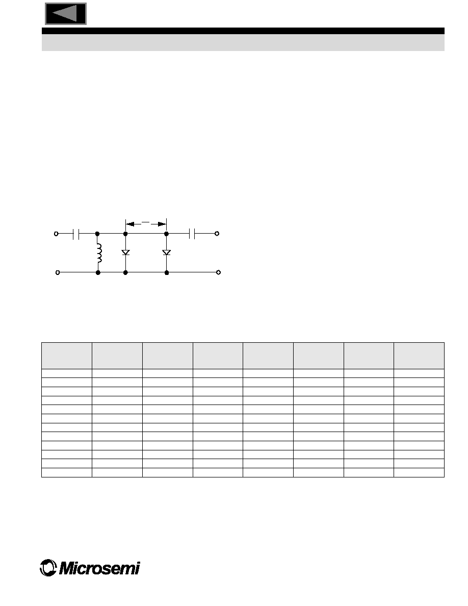
INPUT
DC
RETURN
DC BLOCK
DC BLOCK
CLEAN UP
(FAST)
LIMITER
DIODE
OUTPUT
COARSE
(HIGH
POWER)
LIMITER
DIODE
BASIC TWO-DIODE LIMITER
4
SEMICONDUCTOR OPERATION
75 Technology Drive Lowell, MA 01851 Tel: 978-442-5600 Fax: 978-937-3748
83
Control Devices
TOC

MODEL
NUMBER
MAXIMUM
PEAK
PIN
@1.
µ
S (dBm)
TYPICAL
LEAKAGE
P
out
(dBm)
TYPICAL
THRESHOLD
(dBm)
TYPICAL
INSERTION LOSS
(dB)
MAXIMUM
CW
POWER
(Watts)
GC4701
+50
+22
+10
0.1
2
GC4702
+53
+24
+10
0.2
3
GC4711
+53
+27
+15
0.1
3
GC4712
+56
+29
+15
0.2
4
GC4713
+59
+31
+15
0.2
5
GC4721
+60
+39
+20
0.1
5
GC4722
+63
+41
+20
0.2
10
GC4723
+66
+44
+20
0.2
15
GC4731
+47
+19
+7
0.1
2
GC4732
+50
+22
+7
0.1
3
GC4741
+47
+24
+12
0.1
3
GC4742
+50
+27
+12
0.1
4
LIMITER DIODES
RATINGS
Maximum Leakage Current:
0.5µA at 80% of
minimum rated
breakdown
Operating Temperature:
55∞C to +150∞C
TYPICAL PERFORMANCE
Notes:
1. Available in standard case styles 30, 35, 42 AND 45. When ordering specify the desired case style by adding its number as a suffix to the
basic part number. Some other case styles are available on request.
TYPICAL LIMITER PERFORMANCE RATINGS: T
A
= 25∞C
POWER OUT (mw)
+1.0
+10
+100
+1000
10,000
+10
+20
+30
+40
+50
+60
PEAK POWER INPUT (dBm)
30dB
20dB
10dB
0dB
GC4701, 4741
GC4721
THRESHOLD
0
+1
+2
+3
+4
+5
+6
+7
+8
+9
2
4
6
8
10
12
14
16
18
LEAKAGE POWER ABOVE 1.0GHz (dB)
FREQUENCY (GHz)
GC4701, 4741
GC4721
SEMICONDUCTOR OPERATION
75 Technology Drive Lowell, MA 01851 Tel: 978-442-5600 Fax: 978-937-3748
84
Control Devices
TOC