10 WATT ZENER DIODES
S C O T T S D A L E D I V I S I O N
1N2970 thru 1N3015B
and 1N3993 thru 1N4000A
W
W
W
.
Mi
c
r
o
s
e
m
i
.
C
O
M
1N2
970 ≠ 1
N
3015B
1N3
993 ≠ 1
N
4000A
DESCRIPTION
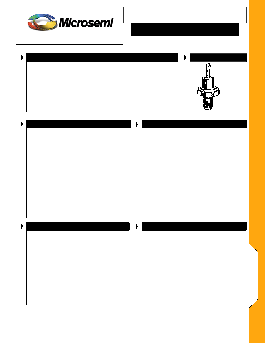
APPEARANCE
These high power 10 W Zener diodes represented by the JEDEC
registered 1N2970 thru 1N3015B and 1N3993 thru 1N4000A series provide
voltage regulation in a selection over a 3.9 V to 200 V broad range of
voltages. They may be operated up to 10 W with adequate mounting and
heat sinking with their low thermal resistance. These Zeners are also
available in JAN, JANTX, JANTXV military qualifications. Microsemi also
offers numerous other Zener products to meet higher and lower power
applications.
DO-4
(DO-203AA)
IMPORTANT: For the most current data, consult MICROSEMI's website:
http://www.microsemi.com
FEATURES
APPLICATIONS / BENEFITS
∑
JEDEC registered 1N2970 thru 1N3015B and
1N3993 thru 1N4000A
∑
Internal solder bond construction
∑
Hermetically sealed (welded)
∑
Zener Voltage 3.9V to 200V.
∑
Also available in JAN, JANTX, and JANTXV
qualifications per MIL-PRF-19500/124 by
adding the JAN, JANTX, or JANTXV prefixes to
part numbers for desired level of screening;
(e.g. JANTX1N2970B, JANTXV1N3996A, etc.
∑
Standard polarity is anode to case (stud) for
1N2970 thru 1N3015B and cathode to case for
1N3993 thru 1N4000A
∑
Reverse polarity is cathode to case for 1N2970
thru 1N3015B and anode to case for 1N3993
thru 1N4000A by designating R suffix, e.g.
1N2970RB, 1N3993RA, etc.
∑
Consult factory for surface mount equivalents
∑
Regulates voltage over a broad operating
current and temperature range
∑
Standard voltage tolerances are +/- 5% with B
suffix, +/-10% with an A suffix, and +/-20% with
no suffix
∑
Consult factory for +/-2% or +/-1% voltage
tolerance with a C or D suffix respectively
∑
Reverse polarity available
∑
Nonsensitive to ESD per MIL-STD-750 Method
1020
∑
Inherently radiation hard as described in
Microsemi MicroNote 050
MAXIMUM RATINGS
MECHANICAL AND PACKAGING
∑ Junction Temperatures: -65
o
C to +175
o
C
∑ Storage Temperatures: -65
o
C to +200
o
C
∑ DC Power Dissipation: 10 Watts
∑ Power Derating: 80 mW/
o
C above 50
o
C
∑ Forward Voltage @ 2.0 A: 1.5 Volts
∑ THERMAL RESISTANCE: 10
o
C/W (typical)
junction to case (stud)
∑ Solder temperatures: 260
o
C for 10 s (max)
∑ CASE: Industry Standard DO-4, (DO-203AA), 7/16"
Hex, stud with 10-32 threads, welded, hermetically
sealed metal and glass
∑ FINISH: All external surfaces are corrosion
resistant and terminal solderable
∑ POLARITY: 1N3993 ≠ 1N4000: Std. Polarity is
cathode to stud. Reverse polarity (anode to stud)
indicated by suffix "R"
1N2970 ≠ 1N3015: Std. Polarity is anode to stud.
Reverse polarity indicated by suffix "R"
∑ WEIGHT: 7.5 grams
∑ MOUNTING HARDWARE: Consult factory for
optional insulator, bushing solder terminal,
washers, and nut
∑ See package dimension on last page
Microsemi
Scottsdale Division
8700 E. Thomas Rd. PO Box 1390, Scottsdale, AZ 85252 USA, (480) 941-6300, Fax: (480) 947-1503
Page 1
Copyright
2003
11-12-2003 REV A

10 WATT ZENER DIODES
S C O T T S D A L E D I V I S I O N
1N2970 thru 1N3015B
and 1N3993 thru 1N4000A
W
W
W
.
Mi
c
r
o
s
e
m
i
.
C
O
M
1N2
970 ≠ 1
N
3015B
1N3
993 ≠ 1
N
4000A
ELECTRICAL CHARACTERISTICS @ 30
o
C Case Temperature
MAX. DYNAMIC
IMPEDANCE
(Note 3)
MAX**
REVERSE
CURRENT
I
R
@ V
R
JEDEC
TYPE NO.
(Note 1)
NOMINAL
ZENER
VOLTAGE
V
Z
@
I
ZT
(Note 2)
Volts
ZENER
TEST
CURRENT
(
I
ZT
)
mA
Z
ZT
@ I
ZT
OHMS
Z
ZK
@
1mA (I
ZK
)
OHMS
MAX. DC ZENER
CURRENT
(
I
ZM
) @ 75
o
C
Stud Temp.
(Note 4)
mA
TYPICAL
TEMP.
COEFF.
VZ
%/
o
C
µA Volts
POLARITY
1N3993A
1N3994A
1N3995A
1N3996A
1N3997A
1N3998A
1N3999A
1N4000A
3.9
4.3
4.7
5.1
5.6
6.2
6.8
7.5
640
580
530
490
445
405
370
335
2.0
1.5
1.2
1.1
1.0
1.1
1.2
1.3
400
400
500
550
600
750
500
250
2380
2130
1940
1780
1620
1460
1330
1210
-.046
-.033
-.015
+/-.010
+.030
+.049
+.040
+.045
100
100
50
10
10
10
10
10
0.5
0.5
1.0
1.0
1.0
2.0
2.0
3.0
STD.
POLARITY
CATHODE
TO
STUD
1N2970B
1N2971B
1N2972B
1N2973B
1N2974B
1N2975B
6.8
7.5
8.2
9.1
10
11
370
335
305
275
250
230
1.2
1.3
1.5
2.0
3
3
500
250
250
250
250
250
1320
1180
1040
960
860
780
.040
.045
.048
.051
.055
.060
150
100
50
25
25
10
5.2
5.7
6.2
6.9
7.6
8.4
1N2976B
1N2977B
1N2978B
1N2979B
1N2980B
1N2981B
12
13
14
15
16
17
210
190
180
170
155
145
3
3
3
3
4
4
250
250
250
250
250
250
720
660
600
560
530
500
.065
.065
.070
.070
.070
.075
10
10
10
10
10
10
9.1
9.9
10.5
11.4
12.2
13.0
1N2982B
1N2983B
1N2984B
1N2985B
1N2986B
1N2987B
18
19
20
22
24
25
140
130
125
115
105
100
4
4
4
5
5
6
250
250
250
250
250
250
460
440
420
380
350
310
.075
.075
.075
.080
.080
.080
10
10
10
10
10
10
13.7
14.0
15.2
16.7
18.2
18.2
1N2988B
1N2989B
1N2990B
1N2991B
1N2992B
1N2993B
27
30
33
36
39
43
95
85
75
70
65
60
7
8
9
10
11
12
250
300
300
300
300
400
300
280
260
230
210
195
.085
.085
.085
.085
.090
.090
10
10
10
10
10
10
20.6
22.8
25.1
27.4
29.7
32.7
1N2994B
1N2995B
1N2996B
1N2997B
1N2998B
1N3099B
1N3000B
45
47
50
51
52
56
62
55
55
50
50
50
45
40
13
14
15
15
15
16
17
400
400
500
500
500
500
600
185
175
165
160
160
150
130
.090
.090
.090
.090
.090
.090
.090
10
10
10
10
10
10
10
33.0
35.8
36.0
38.8
39.0
42.6
47.1
1N3001B
1N3002B
1N3003B
1N3004B
1N3005B
1N3006B
1N3007B
68
75
82
91
100
105
110
37
33
30
28
25
25
23
18
22
25
35
40
45
55
600
600
700
800
900
1000
1100
120
110
100
85
80
75
72
.090
.090
.090
.090
.090
.095
.095
10
10
10
10
10
10
10
51.7
56.0
62.2
69.2
76.0
76.0
83.6
1N3008B
1N3009B
1N3010B
1N3011B
1N3012B
1N3013B
1N3014B
1N3015B
120
130
140
150
160
175
180
200
20
19
18
17
16
14
14
12
75
100
125
175
200
250
260
300
1200
1300
1400
1500
1600
1750
1850
2000
67
62
58
54
50
46
45
40
.095
.095
.095
.095
.095
.095
.095
.100
10
10
10
10
10
10
10
10
91.2
98.8
100.0
114.0
121.6
135.0
136.8
152.0
STD.
POLARITY
ANODE
TO STUD
*JEDEC Registered Data. **Not JEDEC Data.
Have JAN and JANTX Qualifications to MIL-PRF-19500/124. See further notes on following page
Microsemi
Scottsdale Division
8700 E. Thomas Rd. PO Box 1390, Scottsdale, AZ 85252 USA, (480) 941-6300, Fax: (480) 947-1503
Page 2
Copyright
2003
11-12-2003 REV A
10 WATT ZENER DIODES
S C O T T S D A L E D I V I S I O N
1N2970 thru 1N3015B
and 1N3993 thru 1N4000A
W
W
W
.
Mi
c
r
o
s
e
m
i
.
C
O
M
1N2
970 ≠ 1
N
3015B
1N3
993 ≠ 1
N
4000A
NOTES: 1. 1N3993 - 1N4000 series: suffix A indicates +/-5% tolerance, no suffix indicates +/-10% tolerance. 1N2970 ≠ 1N3015 series: suffix B
indicates +/- 5% tolerance, suffix A indicates +/-10%, no suffix indicates +/-20% tolerance. If tighter tolerance is required, consult
factory.
2.
The electrical characteristics are measured after allowing the device to stabilize for 90 seconds with 30
o
C Base temperature.
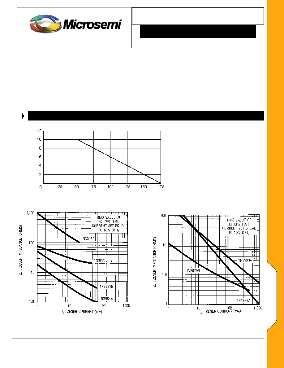
3.
The zener impedance (Z
ZT
) is derived from the 60 Hz ac voltage, which results when an ac current having an rms value equal to 10% of
the dc zener current (I
ZT
or I
ZK
) is superimposed on I
ZT
or I
ZK
. When making zener impedance measurements at the I
ZK
test point, it may
be necessary to insert a 60 Hz band pass filter between the diode and voltmeter to avoid errors resulting from low level noise signals. A
curve showing the variation of zener impedance vs. zener current for three representative types is shown in Figures 2 and 3. Also see
Microsemi MicroNote 202.
4.
These values of I
ZM
may be exceeded in the case of individual diodes. The values shown are calculated for the worst case that is a unit
of +/-5% tolerance at the high voltage end of its tolerance range. Allowance has also been made for the rise in zener voltage above V
ZT
,
which results from zener impedance and the increase in junction temperature as power dissipation approaches 10 watts.
GRAPHS
FIGURE 1
Pd Rated Po
w
e
r
Dissipation -
W
a
tts
Stud Temperature (
o
C)
Power Derating Curve
FIGURE 2
FIGURE 3
Typical Zener Impedance vs. Zener Current
Typical Zener Impedance vs. Zener Current
For Types Shown
For Types Shown
Microsemi
Scottsdale Division
8700 E. Thomas Rd. PO Box 1390, Scottsdale, AZ 85252 USA, (480) 941-6300, Fax: (480) 947-1503
Page 3
Copyright
2003
11-12-2003 REV A
10 WATT ZENER DIODES
Microsemi
Scottsdale Division
8700 E. Thomas Rd. PO Box 1390, Scottsdale, AZ 85252 USA, (480) 941-6300, Fax: (480) 947-1503
Page 4
Copyright
2003
11-12-2003 REV A
W
W
W
.
Mi
c
r
o
s
e
m
i
.
C
O
M
S C O T T S D A L E D I V I S I O N
1N2970 thru 1N3015B
and 1N3993 thru 1N4000A
1N2
970 ≠ 1
N
3015B
1N3
993 ≠ 1
N
4000A
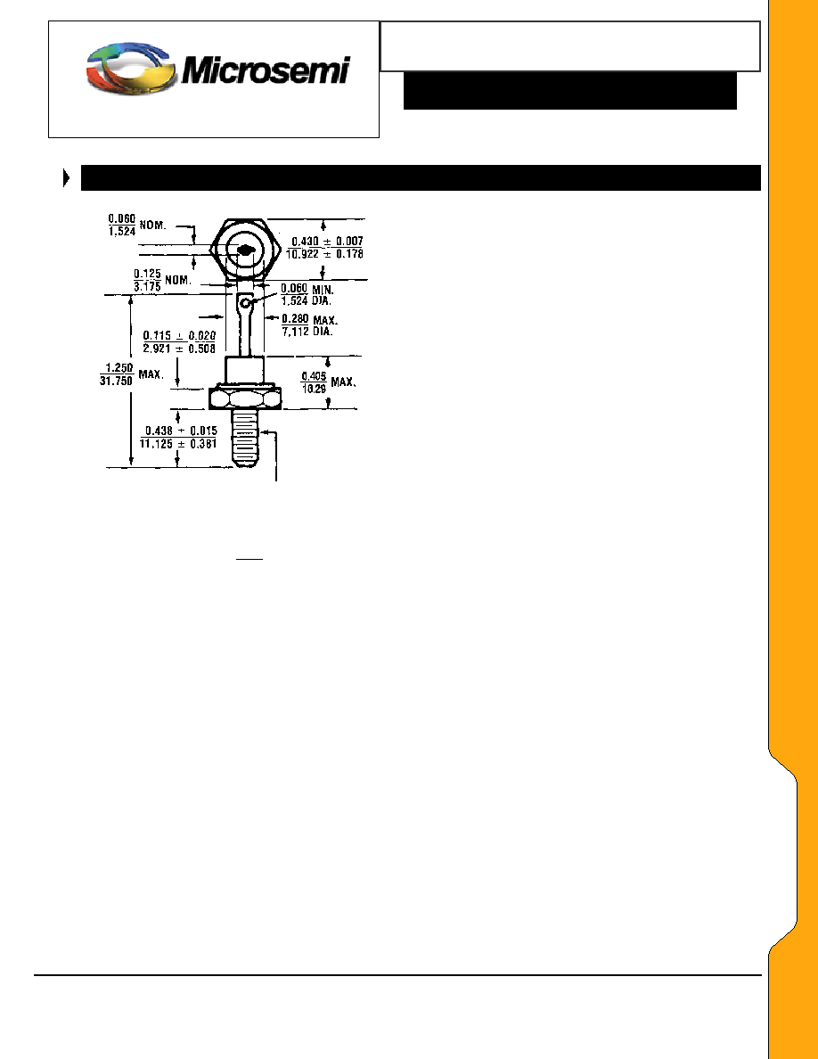
PACKAGE DIMENSIONS
10-32 UNF-2A (MOD) PITCH DIA.
MIN. .1658 MAX. .1697 TO WITH-
STAND A TORQUE UP TO 30 IN-LB.
WHEN NUT IS TIGHTENED ON STUD
All dimensions in: INCH
mm