Silicon 500 mW Zener Diodes
Microsemi
Scottsdale Division
8700 E. Thomas Rd. PO Box 1390, Scottsdale, AZ 85252 USA, (480) 941-6300, Fax: (480) 947-1503
Page 1
Copyright
2003
10-31-2003 REV B
W
W
W
.
Mi
c
r
o
s
e
m
i
.
C
O
M
S C O T T S D A L E D I V I S I O N
1N746 thru 1N759A, -1 and
1N4370 thru 1N4372A, -1 DO-35
1N746 ≠759A
1N4370 ≠ 4372A (DO-35)
FEATURES
APPLICATIONS / BENEFITS
∑ JEDEC registered 1N746 thru 1N759A and 1N4370
thru 1N4372A series
∑ Internal metallurgical bond option available by adding
a "-1" suffix
∑ Also available in JAN, JANTX, and JANTXV
qualifications per MIL-PRF-19500/127 by adding the
JAN, JANTX, or JANTXV prefixes to part numbers for
desired level of screening as well as ≠1" suffix; (e.g.
JANTX1N751A-1, JANTXV1N758C-1, etc.)
∑ Military Surface Mount equivalents also available in
DO-213AA by adding a UR-1 suffix in addition to the
JAN, JANTX, and JANTXV prefix; e.g.
JANTX1N962BUR-1 (see separate data sheet)
∑ Commercial Surface Mount equivalents available as
MLL746 to MLL759A and MLL4370 to MLL4372A
including the "-1" suffix in the DO-213AA MELF style
package (consult factory for others)
∑ DO-7 glass body axial-leaded Zener equivalents are
also available
∑ Regulates voltage over a broad operating
current and temperature range
∑ Selection from 2.4 to 12 V
∑ Standard voltage tolerances are plus/minus 5%
with A suffix identification and 10 % with no suffix
∑ Tight tolerances available in plus or minus 2%
or 1% with C or D suffix respectively
∑ Flexible axial-lead mounting terminals
∑ Nonsensitive to ESD per MIL-STD-750 Method
1020
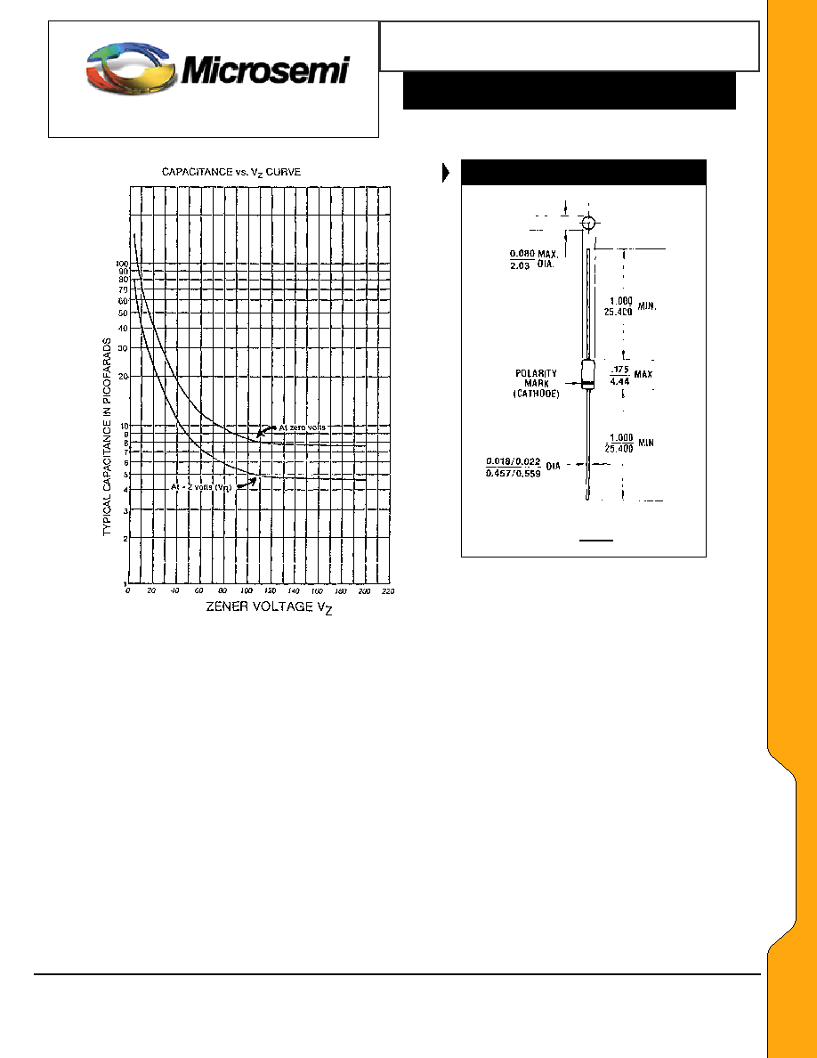
∑ Minimal capacitance (see Figure 3)
∑ Inherently radiation hard as described in Microsemi
MicroNote 050
MAXIMUM RATINGS
MECHANICAL AND PACKAGING
∑ Operating and Storage temperature: -65
∫
C to +175
∫
C
∑ Thermal Resistance: 250
∫
C/W junction to lead at 3/8
(10 mm) lead length from body, or 310
∫
C/W junction to
ambient when mounted on FR4 PC board (1 oz Cu)
with 4 mm
2
copper pads and track width 1 mm, length
25 mm
∑ Steady-State Power: 0.5 watts at T
L
< 50
o
C 3/8 inch
(10 mm) from body or 0.48 W at T
A
< 25
∫
C when
mounted on FR4 PC board as described for thermal
resistance above (also see Figure1)
∑ Forward voltage @200 mA: 1.1 volts
∑ Solder Temperatures: 260
∫
C for 10 s (max)
∑ CASE: Hermetically sealed axial-lead glass
DO-35 (DO-204AH) package
∑ TERMINALS: Leads, tin-lead plated solderable per
MIL-STD-750, method 2026
∑ POLARITY: Cathode indicated by band. Diode to
be operated with the banded end positive with
respect to the opposite end for Zener regulation
∑ MARKING: Part number
∑ TAPE & REEL option: Standard per EIA-296 (add
"TR" suffix to part number)
∑ WEIGHT: 0.2 grams
∑ See package dimensions on last page
DESCRIPTION
APPEARANCE
The popular 1N746 thru 1N759A and 1N4370 thru 1N4372A series of 0.5
watt Zener Voltage Regulators provides a selection from 2.4 to 12 volts in
standard 5% or 10% tolerances as well as tighter tolerances identified by
different suffix letters on the part number. These glass axial-leaded DO-35
Zeners are also available with an internal-metallurgical-bond option by
adding a "-1" suffix. These are also available in JAN, JANTX, and JANTXV
military qualifications. Microsemi also offers numerous other Zener
products to meet higher and lower power applications.
DO-35
(DO-204AH)
IMPORTANT: For the most current data, consult MICROSEMI's website:
http://www.microsemi.com
Silicon 500 mW Zener Diodes
S C O T T S D A L E D I V I S I O N
1N746 thru 1N759A, -1 and
1N4370 thru 1N4372A, -1 DO-35
W
W
W
.
Mi
c
r
o
s
e
m
i
.
C
O
M
ELECTRICAL CHARACTERISTICS* @ 25
o
C
MAXIMUM REVERSE
CURRENT I
R
@ V
R
= 1 VOLT
NOMINAL
ZENER
VOLTAGE
V
Z
@
I
ZT
(NOTE 2)
ZENER
TEST
CURRENT
I
ZT
MAXIMUM
ZENER
IMPEDANCE
Z
ZT
@
I
ZT
(NOTE 3)
@25∫C
@+150∫C
MAXIMUM
ZENER
CURRENT
I
ZM
(NOTE 4)
TYPICAL
TEMP COEFF.
OF ZENER
VOLTAGE
VZ
JEDEC
TYPE NO.
(NOTE1)
VOLTS mA OHMS
µA
µA
mA %/
o
C
1N4370
1N4371
1N4372
2.4
2.7
3.0
20
20
20
30
30
29
100
75
50
200
150
100
150
135
120
-.085
-.080
-.075
1N746
1N747
1N748
3.3
3.6
3.9
20
20
20
28
24
23
10
10
10
30
30
30
110
100
95
-.066
-.058
-.046
1N749
1N750
1N751
1N752
4.3
4.7
5.1
5.6
20
20
20
20
22
19
17
11
2
2
1
1
30
30
20
20
85
75
70
65
-.033
-.015
+/-.010
+.030
1N753
1N754
1N755
1N756
6.2
6.8
7.5
8.2
20
20
20
20
7
5
6
8
.1
.1
.1
.1
20
20
20
20
60
55
50
45
+.049
+.053
+.057
+.060
1N757
1N758
1N759
9.1
10.0
12.0
20
20
20
10
17
30
.1
.1
.1
20
20
20
40
35
30
+.061
+.062
+.062
* JEDEC Registered Data
NOTE 1: Standard tolerance on JEDEC types shown is +/- 10%. Suffix letter A denotes +/- 5% tolerance; suffix
letter C denotes +/- 2%; and suffix letter D denotes +/- 1% tolerance.
NOTE 2: Voltage measurements to be performed 20 seconds after application of dc test current.
NOTE 3: Zener impedance derived by superimposing on
I
ZT
, a 60 cps, rms ac current equal to 10%
I
ZT
(2mA ac). See MicroNote 202 for
typical zener Impedance variation with different operating currents.
NOTE 4: Allowance has been made for the increase in
V
Z
due to Z
Z
and for the increase in junction temperature as the unit approaches
thermal equilibrium at the power dissipation of 400 mW.
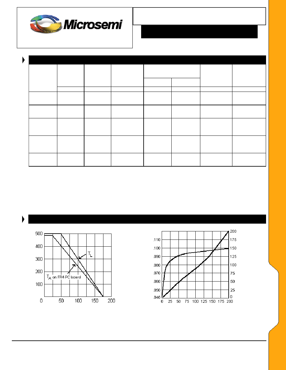
GRAPHS
1N746 ≠759A
1N4370 ≠ 4372A (DO-35)
RATED P
O
W
E
R DISSIPATION -
mW
T
E
M
P
E
R
A
T
U
R
E
C
O
E
F
F
I
C
I
E
N
T
m
V
/
o
C
TEMPERATURE
COEFF
I
CIENT
%
/
∫
C
T
L
≠ LEAD TEMPERATURE (
o
C) 3/8" FROM BODY or
NOMINAL ZENER VOLTAGE (VOLTS)
T
A
on FR4 PC BOARD
FIGURE
1
FIGURE
2
POWER DERATING CURVE
ZENER VOLTAGE TEMPERATURE
COEFFICIENT vs. ZENER VOLTAGE
Microsemi
Scottsdale Division
8700 E. Thomas Rd. PO Box 1390, Scottsdale, AZ 85252 USA, (480) 941-6300, Fax: (480) 947-1503
Page 2
Copyright
2003
10-31-2003 REV B
Silicon 500 mW Zener Diodes
Microsemi
Scottsdale Division
8700 E. Thomas Rd. PO Box 1390, Scottsdale, AZ 85252 USA, (480) 941-6300, Fax: (480) 947-1503
Page 3
Copyright
2003
10-31-2003 REV B
W
W
W
.
Mi
c
r
o
s
e
m
i
.
C
O
M
S C O T T S D A L E D I V I S I O N
1N746 thru 1N759A, -1 and
1N4370 thru 1N4372A, -1 DO-35
1N746 ≠759A
1N4370 ≠ 4372A (DO-35)
PACKAGE DIMENSIONS
All dimensions in: INCH
mm
FIGURE
3
CAPACITANCE vs. ZENER VOLTAGE
(TYPICAL)