MSC1061.PDF 5-21-99 DSW1N5610 <-> (35436)
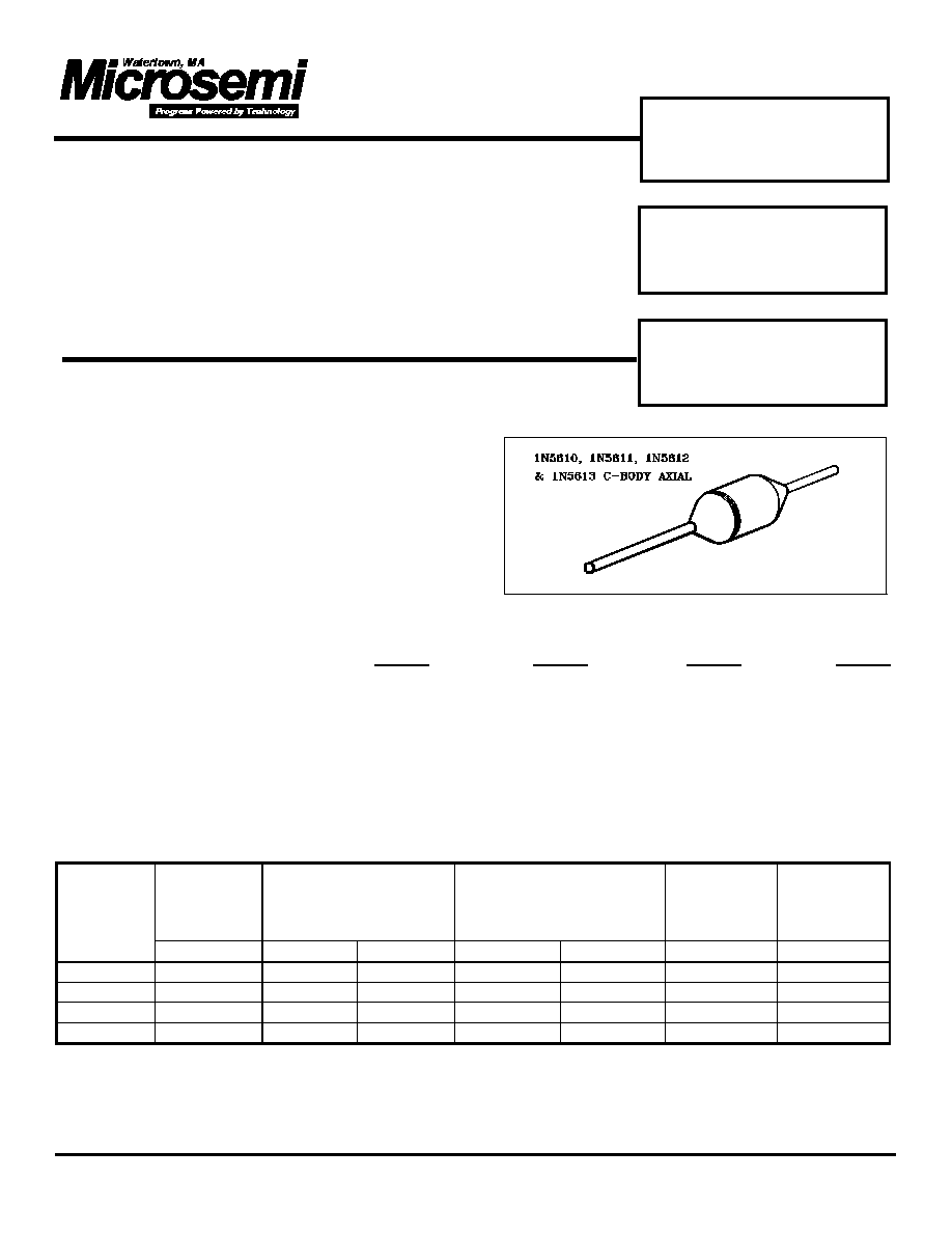
1N5610
1N5611
1N5612, 1N5613
Features
Features
∑
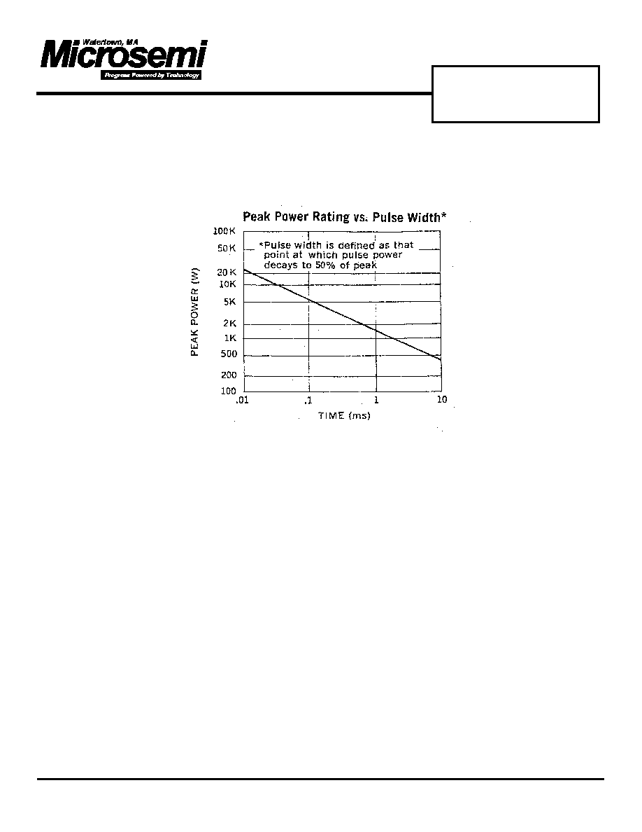
1500 Watts for 1 ms Pulse Power Capability
∑
Small Physical Size
∑
Designed for MIL-STD-704A Applications
Description
Zener diodes with a high surge capability
qualified to MIL-S-19500/434
Absolute Maximum Ratings ( @ 25
∞
C unless noted )
1N5610 1N5611 1N5612 1N5613
Forward Surge Current, 200 A 200 A 200 A 200 A
Zener Surge Current, @ 25C 32.0 A 24.0 A 19.0 A 5.7 A
Zener Surge Current @ 150C 5.5 A 4.8 A 3.2 A 1.0 A
Storage and Operating Temperature -65C to + 175C
Zener Voltage See Electrical Characteristics
Surge Power See Graphs
Electrical Characteristics (T = 25
∞
C unless otherwise noted)
Min. Zener
Voltage
Vz @ 1Ma
Max. Zener
Voltage
Vz @ Is
MAX.
Reverse Leakage
Current
I
R
@ V
R
MAX.
Forward V
@ 100 A
Typical
Temp.
Coefficient
DEVICE
TYPE
Volts
Volts
Amps
µµ
A
Volts
Volts
% /
∞∞
C
1N5610*
33.0
47.5
32.0
5.0
30.5
4.8
.093
1N5611*
43.7
63.5
24.0
5.0
40.3
4.8
.094
1N5612*
54.0
78.5
19.0
5.0
49.0
4.8
.096
1N5613*
191
265
5.7
5.0
175
4.8
.100
NOTES: * Available as JAN, JANTX and JANTXV
Duration of applied current
300 ms, Duty cycle
2%.
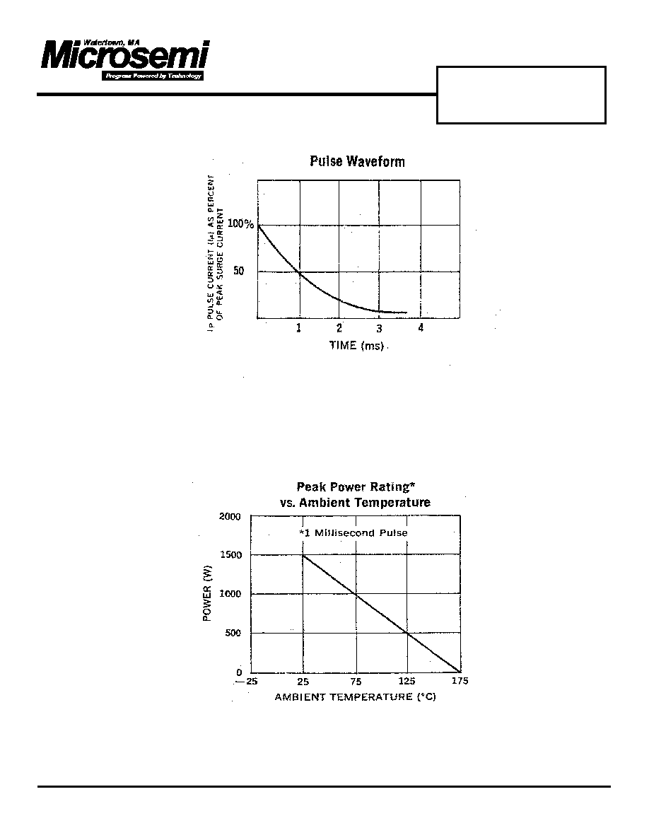
Use a pulse which decays exponentially to 50 % of peak value during 1 ms. (See " Pulse Waveform " graph).
Peak Sinusoidal surge current of 8.3 ms duration, non repetitive
TRANSIENT
SUPPRESSOR
DIODE
POWER ZENER
RECTIFIER
JAN, JANTX, JANTXV
580 Pleasant St.
Watertown, MA 02472
PH: (617) 926-0404
FAX: (617) 924-1235
MSC1061.PDF 5-21-99 DSW1N5610 <-> (35436)
1N5610
1N5611
1N5612, 1N5613
Applications
Voltage transients can be suppressed with series elements, shunt elements or a combination of both. These
elements may be passive or active. For low & medium power applications, a series resistor & zener clamp offer
several attractive features:
1. Simplicity of design.
2. High reliability.
3. Fast response time.
The 1N5610 series will suppress the following transients (defined by MIL-S-704A) without using any series
limiting resistance; (except as noted in line #3 below)
1. All 600 V transients (category 1 in chart below).
2. All 80 V transients except those generated by the main voltage regulator (category 2 in chart below).
3. Over-voltage transients from the main voltage regulator (category 3 in chart below) will be suppressed if:
a. A 20 ohm series limiting resistor is used, or-
b. No series resistance is used & the zener is protected within 500
µµ
s, using (for example) an SCR crowbar.
The above statements are based on the source impedances & dv/dt characteristics as given in ARINC* spec#
413; entitled "Guidance for Aircraft Electrical Power Utilization & Transient Protection. This report further
defines MIL-STD-704A in regard to large aircraft electrical systems.
These surge suppressors are useful in a varierty of other applications where semiconductor devices must
function in an environment subject to extremely high, but short term surges.
* ARINC stands for Aeronautical Radio Incorporated; Annapolis, Maryland 21401
Cate-
gory
#
Source
of
Trans.
Max.
Ampli-
tude
Duration
of
Trans.
Min.
Imped-
ance
dv
over
dt
1
Induc-
tive
Swtchg
600 V
10
µµ
s
50 ohm
---
2
BUS
Switch-
ing
80 V
10 ms
15 ohm
---
3
Main
Volt.
Reg.
80 V
10 ms
0.2 ohm
50V/ms