1500 WATT LOW CAPACITANCE
TRANSIENT VOLTAGE SUPPRESSOR
S C O T T S D A L E D I V I S I O N
LC6.5 thru LC170A
W
W
W
.
Mi
c
r
o
s
e
m
i
.
C
O
M
LC6.5
t
hru
L
C170A
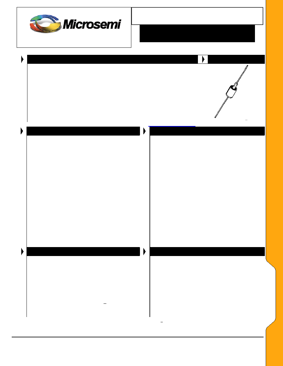
DESCRIPTION
APPEARANCE
This hermetically sealed Transient Voltage Suppressor (TVS) product family
includes a rectifier diode element in series and opposite direction to achieve low
capacitance performance below 100 pF (see Figure 2). The low level of TVS
capacitance may be used for protecting higher frequency applications in
inductive switching environments or electrical systems involving secondary
lightning effects per IEC61000-4-5 as well as RTCA/DO-160D or ARINC 429 for
airborne avionics. With virtually instantaneous response, they also protect from
ESD and EFT per IEC61000-4-2 and IEC61000-4-4. If bipolar transient
capability is required, two of these low capacitance TVS devices may be used in
parallel in opposite directions (anti
-
parallel) for complete ac protection as shown
in Figure 6.
DO-13
(DO-202AA)
IMPORTANT: For the most current data, consult MICROSEMI's website:
http://www.microsemi.com
FEATURES
APPLICATIONS / BENEFITS
� Unidirectional low-capacitance TVS series for flexible
thru-hole mounting (for bidirectional see Figure 4)
� Suppresses transients up to 1500 watts @ 10/1000 �s
(see Figure 1)*
� Clamps transient in less than 100 pico seconds
� Working voltage (V
WM
) range 6.5 V to 170 V
� Hermetic sealed DO-13 metal package
� Options for screening in accordance with MIL-PRF-
19500 for JAN, JANTX, JANTXV, and JANS are also
available by adding MQ, MX, MV, MSP prefixes
respectively to part numbers, e.g. MXLC6.5A, etc.
� Surface mount equivalent packages also available as
SMCJLCE6.5 - SMCJLCE170A or SMCGLCE6.5 -
SMCGLCE170A in separate data sheet (consult
factory for other surface mount options)
� Plastic axial-leaded equivalents available in the
LCE6.5 - LCE170A series in separate data sheet
� Protection from switching transients and induced RF
� Protection for aircraft fast data rate lines per select
level waveforms in RTCA/DO-160D & ARINC 429
� ESD & EFT protection per IEC 61000-4-2 and -4-4
� Secondary lightning protection per IEC61000-4-5 with
42 Ohms source impedance:
Class 1: LC6.5 to LC170A
Class 2: LC6.5 to LC150A
Class 3: LC6.5 to LC70A
Class 4: LC6.5 to LC36A
� Secondary lightning protection per IEC61000-4-5 with
12 Ohms source impedance:
Class 1 : LC6.5 to LC90A
Class 2: LC6.5 to LC45 A
Class 3: LC6.5 to LC22A
Class 4: LC6.5 to LC11A
� Secondary lightning protection per IEC61000-4-5 with
2 Ohms source impedance:
Class 2: LC6.5 to LC20A
Class 3: LC6.5 to LC10A
� Inherently radiation hard per Microsemi MicroNote 050
MAXIMUM RATINGS
MECHANICAL AND PACKAGING
� 1500 Watts at 10/1000 �s
with repetition rate of 0.01% or
less*
at lead temperature (T
L
) 25
o
C (see Figs. 1, 2, & 4)
� Operating & Storage Temperatures: -65
o
to +175
o
C
� THERMAL RESISTANCE: 50
o
C/W (Typical) junction to
lead at 0.375 inches (10 mm) from body or 110
o
C/W
junction to ambient when mounted on FR4 PC board
with 4 mm
2
copper pads (1 oz) and track width 1 mm,
length 25 mm
� DC Power Dissipation
*
: 1 Watt at T
L
< +125
o
C 3/8" (10
mm) from body (see derating in Fig 3 and note below)
� Solder Temperatures: 260
o
C for 10 s (maximum)
� CASE: DO-13 (DO-202AA), welded, hermetically
sealed metal and glass
� FINISH: All external metal surfaces are Tin-Lead
plated and solderable per MIL-STD-750 method 2026
� POLARITY: Cathode connected to case as shown by
diode symbol (cathode positive for normal operation)
� MARKING: Part number and polarity diode symbol
� WEIGHT: 1.4 grams. (Approx)
� TAPE & REEL option: Standard per EIA-296 (add
"TR" suffix to part number)
� See package dimension on last page
*
TVS devices are not typically used for dc power dissipation and are instead operated < V
WM
(rated standoff voltage) except for transients that briefly
drive the device into avalanche breakdown (V
BR
to V
C
region) of the TVS element. Also see Figures 3 and 4 for further protection details in rated peak
pulse power for unidirectional and bidirectional configurations respectively.
Microsemi
Scottsdale Division
8700 E. Thomas Rd. PO Box 1390, Scottsdale, AZ 85252 USA, (480) 941-6300, Fax: (480) 947-1503
Page 1
Copyright
2002
10-21-2004 REV C
1500 WATT LOW CAPACITANCE
TRANSIENT VOLTAGE SUPPRESSOR
S C O T T S D A L E D I V I S I O N
LC6.5 thru LC170A
W
W
W
.
Mi
c
r
o
s
e
m
i
.
C
O
M
LC6.5
t
hru
L
C170A
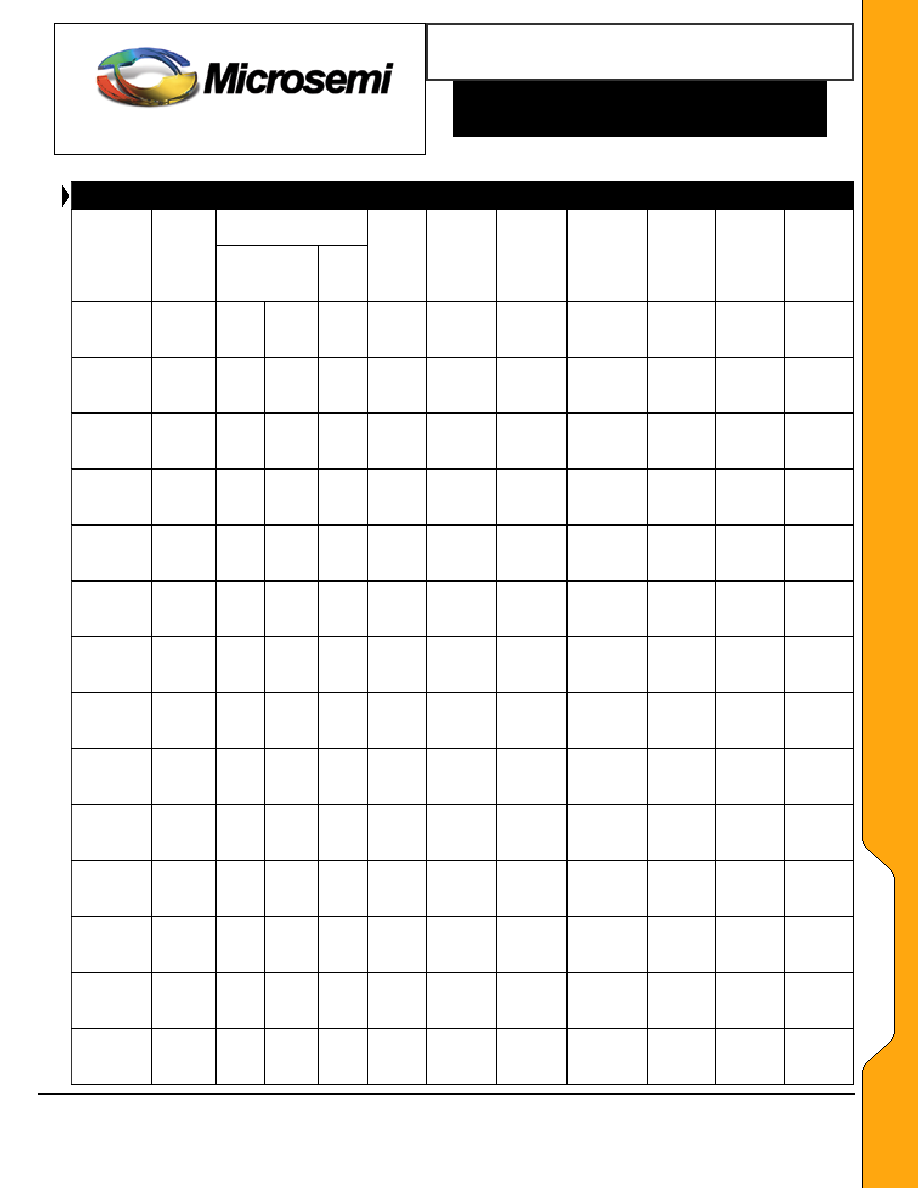
BREAKDOWN VOLTAGE
MICROSEMI
PART
NUMBER
REVERSE
STANDOFF
VOLTAGE
V
WM
VOLTS
V
(BR)
VOLTS
MIN
MAX
@
I
(BR)
mA
MAXIMUM
STANDBY
CURRENT
I
D @
V
WM
�A
MAXIMUM
CLAMPING
VOLTAGE
V
C
@ I
PP
VOLTS
MAXIMUM
PEAK
PULSE
CURRENT
I
PP @
10/1000 �s
AMPS
CAPACI-
TANCE
@ 0
Volts
pF
WORKING
INVERSE
BLOCKING
VOLTAGE
V
WIB
VOLTS
INVERSE
BLOCKING
LEAKAGE
CURRENT
I
IB @
V
WIB
�A
PEAK
INVERSE
BLOCKING
VOLTAGE
VOLTS
V
PIB
VOLTS
LC54
LC54A
LC58
LC58A
54
54
58
58
60.0
60.0
64.4
64.4
73.3
66.3
78.7
71.2
1
1
1
1
5
5
5
5
96.3
87.1
103.0
93.6
15.6
17.2
14.6
16.0
100
100
100
100
150
150
150
150
10
10
10
10
200
200
200
200
LC60
LC60A
LC64
LC64A
60
60
64
64
66.7
66.7
71.1
71.1
81.5
73.7
86.9
78.6
1
1
1
1
5
5
5
5
107.0
96.8
114.0
103.0
14.0
15.5
13.2
14.6
90
90
90
90
150
150
150
150
10
10
10
10
200
200
200
200
LC70
LC70A
LC75
LC75A
70
70
75
75
77.8
77.8
83.3
83.3
95.1
86.0
102.0
92.1
1
1
1
1
5
5
5
5
125
113
134
121
12.0
13.3
11.2
12.4
90
90
90
90
150
150
150
150
10
10
10
10
200
200
200
200
LC80
LC80A
LC90
LC90A
80
80
90
90
88.7
88.7
100
100
108
98.0
122
111
1
1
1
1
5
5
5
5
142
129
160
146
10.6
11.6
9.4
10.3
90
90
90
90
150
150
300
300
10
10
10
10
200
200
200
200
LC100
LC100A
LC110
LC110A
100
100
110
110
111
111
122
122
136
123
149
135
1
1
1
1
5
5
5
5
179
162
196
178
8.4
9.3
7.7
8.4
90
90
90
90
300
300
300
300
10
10
10
10
200
200
400
400
LC120
LC120A
LC130
LC130A
120
120
130
130
133
133
144
144
163
147
176
159
1
1
1
1
5
5
5
5
214
193
231
209
7.0
7.8
6.5
7.2
90
90
90
90
300
300
300
300
10
10
10
10
400
400
400
400
LC150
LC150A
LC160
LC160A
150
150
160
160
167
167
178
178
204
185
218
197
1
1
1
1
5
5
5
5
268
243
287
259
5.6
6.2
5.2
5.8
90
90
90
90
300
300
300
300
10
10
10
10
400
400
400
400
LC170
LC170A
170
170
189
189
231
209
1
1
5
5
304
275
4.9
5.4
90
90
300
300
10
10
400
400
NOTE: TVS are normally selected according to the reverse "Standoff Voltage" (V
WM
) that should be equal to or greater than the dc or continuous
peak operating voltage level.
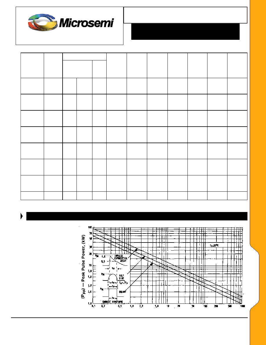
GRAPHS
Pulse Time (tw) in
�s
FIGURE 1
Peak Pulse Power vs.
Pulse Time (t
W
) in
�s
Microsemi
Scottsdale Division
8700 E. Thomas Rd. PO Box 1390, Scottsdale, AZ 85252 USA, (480) 941-6300, Fax: (480) 947-1503
Page 3
Copyright
2002
10-21-2004 REV C
1500 WATT LOW CAPACITANCE
TRANSIENT VOLTAGE SUPPRESSOR
Microsemi
Scottsdale Division
8700 E. Thomas Rd. PO Box 1390, Scottsdale, AZ 85252 USA, (480) 941-6300, Fax: (480) 947-1503
Page 4
Copyright
2002
10-21-2004 REV C
W
W
W
.
Mi
c
r
o
s
e
m
i
.
C
O
M
S C O T T S D A L E D I V I S I O N
LC6.5 thru LC170A
LC6.5
t
hru
L
C170A
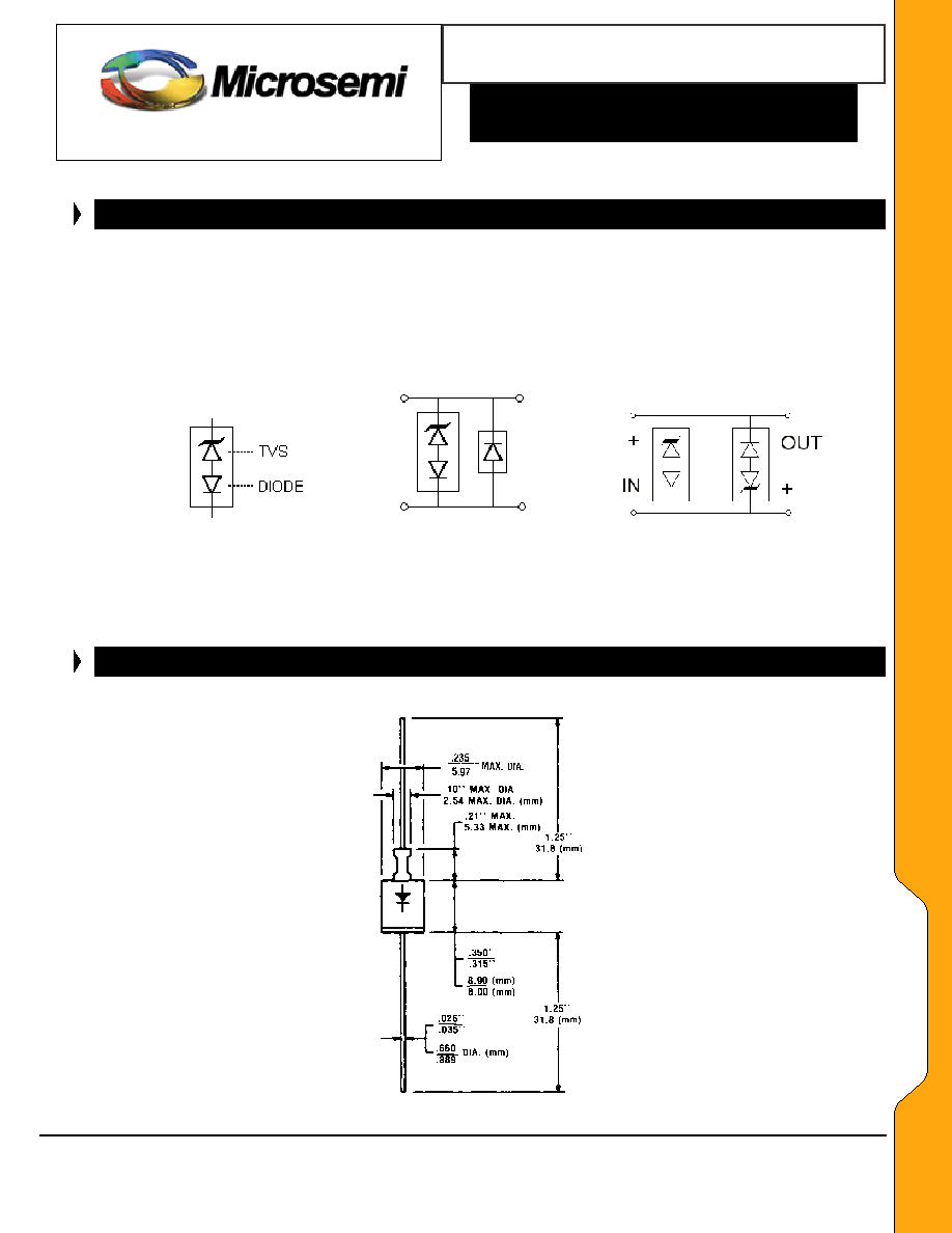
SCHEMATIC APPLICATIONS
The TVS low capacitance device configuration is shown in Figure 2. As a further option for unidirectional applications, an additional low
capacitance rectifier diode may be used in parallel in the same polarity direction as the TVS as shown in Figure 3. In applications where random
high voltage transients occur, this will prevent reverse transients from damaging the internal low capacitance rectifier diode and also provide a
low voltage conducting direction. The added rectifier diode should be of similar low capacitance and also have a higher reverse voltage rating
than the TVS clamping voltage V
C
. The Microsemi recommended rectifier part number is the "LCR80" for the application in Figure 5. If using two
(2) low capacitance TVS devices in anti-parallel for bidirectional applications, this added protective feature for both directions (including the
reverse of each rectifier diode) is also provided. The unidirectional and bidirectional configurations in Figure 3 and 4 will both result in twice the
capacitance of Figure 2.
FIGURE 2
FIGURE 3
FIGURE 4
TVS with internal Low
Optional Unidirectional Optional Bidirectional
Capacitance Diode
configuration (TVS and
configuration (two TVS
separate rectifier diode)
devices in anti-parallel)
in
parallel)
PACKAGE DIMENSIONS
DO-13 (or DO-202AA)