Äîêóìåíòàöèÿ è îïèñàíèÿ www.docs.chipfind.ru
D E S C R I P T I O N
K E Y F E A T U R E S
I RangeMAX Wide Range Dimming
I 8V To 18V Input Voltage Range
I Small Form Factor
I Easy To Use Brightness Control
I MicroAmp SLEEP Mode
I Output Short-Circuit Protection And
Automatic Strike-Voltage Regulation
I Fixed Frequency Operation
I Universal Connector Configuration
A P P L I C A T I O N S
I Hi-Brite Displays
I Desktop Displays
I Low Ambient Light Conditions (i.e. Aircraft
Cabins, Automobile)
I Industrial Applications
B E N E F I T S
I High Efficiency Reduces Heating Problems
I Smooth, Flicker Free 0-100% Full-Range
Brightness Control Gives Your Product A
High Quality Image
I Output Open Circuit Voltage Regulation
Minimizes Corona Discharge For Long Life
And High Reliability
I Power Efficient, "Low Brightness" Capability
Allows For Advanced Power Management
RangeMAX Wide Range Dimming, Dual
Output Inverter. The LXM1621 Direct
Drive
TM
CCFL (Cold Cathode Fluorescent
Lamp) Inverter Modules are specifically de-
signed for driving LCD backlight lamps.
Similar to the LXM1620, the LXM1621 ex-
cels in applications where critical parameters
include very wide range dimmability, high ef-
ficiency and reliable fail-safe design in a small
form factor. These 12 volt input modules are
specifically designed with desktop and indus-
trial applications in mind.
Unlike the LXM1620 or any traditional
dimming CCFL inverters, the LXM1621 pro-
vides the designer a vastly superior display
brightness range. 1000:1+ brightness range
is achievable with a standard LCD display (see
Product Highlight). Our wide range dimming
provides exceptional display readability at less
than 1% of full brightness, allowing both
power savings and low ambient light operat-
ing capability (i.e. "night readable").
RangeMAX Digital Dimming Tech-
nique. Digital dimming provides flicker-free
brightness control in any wide-range dimming
application. Dimming ratios as great as
1000:1 can be achieved. Incorporation of a
video synchronization feature allows wide
ratio dimming without the display distur-
bances and interference seen with competi-
tive products.
The modules are equipped with a dimming
input that permits brightness control from an
external potentiometer or DC voltage source.
The resultant "burst drive" that energizes the
D
IGITAL
D
IMMING
D
UAL
L
AMP
CCFL I
NVERTER
M
ODULE
P
R E L I M I N A R Y
D
A T A
S
H E E T
T
H E
I
N F I N I T E
P
O W E R
O F
I
N N O V A T I O N
LXM1621-xx
P
A T E N T S
P
E N D I N G
lamp was designed specifically to ensure that
no premature lamp degradation occurs (see
"How RangeMAX Works" Section).
Fail-safe Feature For Multiple Lamp
Applications. Our multi-output inverters are
designed to keep your application operating
at near normal brightness in the event that a
lamp fails. This allows the display to remain
"on-line" until lamp replacement is conve-
nient.
Direct Drive Technology. The module
design is based on a new Direct Drive topol-
ogy, which provides a number of cost and
performance advantages. The LXM1621-xx
Direct Drive inverters eliminate the classic
resonant inductor and capacitors, thus reduc-
ing cost and allowing a substantial reduction
in module size.
Universal Connector Configuration.
Linfinity's multiple lamp inverters include a
built in connector array for the most com-
mon LCD lamp configurations.
Additional Features. Other benefits of
this new topology are fixed-frequency opera-
tion and secondary-side strike-voltage regu-
lation.
Strike-voltage regulation minimizes corona
discharge in the output transformer and re-
lated circuitry, providing longer life and higher
reliability. All LXM1621 modules feature
both open and shorted lamp protection.
The LXM1621 is fully customizable (elec-
tronically and mechanically) to specific cus-
tomer requirements.
Copyright © 2000
Rev. 0.6 2/00
1
11861 W
ESTERN
A
VENUE
, G
ARDEN
G
ROVE
, CA. 92841, 714-898-8121, F
AX
: 714-893-2570
L
I N
F
I N I T Y
M
I C R O E L E C T R O N I C S
I
N C
.
RangeMAX
TM
NOTE: For current data & package dimensions, visit our web site: http://www.linfinity.com.
Part Number
Lamp Run Voltage
Lamp Current
LXM1621-01
500 - 750V
RMS
7mA
LXM1621-02
350 - 500V
RMS
6mA
LXM1621-03
350 - 500V
RMS
6.5mA
M O D U L E O R D E R I N F O R M AT I O N

D
IGITAL
D
IMMING
D
UAL
L
AMP
CCFL I
NVERTER
M
ODULE
LXM1621-xx
P R O D U C T D A T A B O O K 1 9 9 6 / 1 9 9 7
Copyright © 2000
Rev. 0.6 2/00
2
P
R E L I M I N A R Y
D
A T A
S
H E E T
P
A T E N T
P
E N D I N G
RangeMAX
TM
A B S O L U T E M A X I M U M R A T I N G S
( N o t e 1 )
Input Supply Voltage (V
IN
) ........................................................................................................................................................ -0.3V to 18V
Output Voltage, no load .............................................................................................................................. Internally Limited to 1800V
RMS
Output Current ............................................................................................................................................. 10.0mA
RMS
(Internally Limited)
Output Power (per Lamp) .................................................................................................................................................................... 6.0W
Input Signal Voltage (BRITE Input) ....................................................................................................................................... -0.3V to 6.5V
Input Signal Voltage (SLEEP, V
SYNC
Inputs) ................................................................................................................................... -0.3V to V
IN
Ambient Operating Temperature .................................................................................................................................................... 0°C to 70°C
Storage Temperature Range ......................................................................................................................................................... -40°C to 85°C
Note 1. Exceeding these ratings could cause damage to the device. All voltages are with respect to Ground.
Currents are positive into, negative out of the specified terminal.
R E C O M M E N D E D O P E R A T I N G C O N D I T I O N S (R.C.)
This module has been designed to operate over a wide range of input and output conditions. However, best efficiency and performance
will be obtained if the module is operated under the condition listed in the 'R.C.' column. Min. and Max. columns indicate values beyond
which the inverter, although operational, will not function optimally.
Input Supply Voltage Range (Functional)
V
IN
Input Supply Voltage (Fully Regulated Lamp Current)
Output Power (per Lamp)
LXM1621-01
P
O
LXM1621-02/-03
Brightness Control Input Voltage Range
V
BRT ADJ
Lamp Operating Voltage
LXM1621-01
V
LAMP
LXM1621-02/-03
Lamp Current (Full Brightnes s - per Lamp)
LXM1621-01
I
OLAMP
LXM1621-02
LXM1621-03
Operating Ambient Temperature Range
T
A
Parameter
Symbol
Units
Recommended Operating Conditions
Min.
R.C.
Max.
8
12
18
V
10.2
12
13.8
V
4
5
W
2.5
3
W
0.0
2.5
V
500
625
750
V
RMS
350
425
500
V
RMS
7.0
mA
RMS
6.0
mA
RMS
6.5
mA
RMS
0
70
°C
E L E C T R I C A L C H A R A C T E R I S T I C S
Unless otherwise specified, these specifications apply over the recommended operating conditions and 25°C ambient temperature for the LXM1621-xx.
Full Bright Lamp Current
1621-01
I
L (MAX)
V
BRT ADJ
= 2.5V
DC
, SLEEP = HIGH, Burst Duty = 100%, V
IN
= 12V
DC
(per Lamp)
1621-02
V
BRT ADJ
= 2.5V
DC
, SLEEP = HIGH, Burst Duty = 100%, V
IN
= 12V
DC
1621-03
V
BRT ADJ
= 2.5V
DC
, SLEEP = HIGH, Burst Duty = 100%, V
IN
= 12V
DC
Minimum Lamp Current (per Lamp)
I
L (MIN)
V
BRT ADJ
= 0V
DC
, SLEEP = HIGH, Burst Duty = 2%, V
IN
= 9V
DC
(Notes 2 & 3)
V
BRT ADJ
= -50mV
DC
, SLEEP = HIGH, Burst Duty = 0.5%, V
IN
= 9V
DC
Lamp Start Voltage
V
LS
0°C < T
A
< 40°C, V
IN
10.8V
DC
Operating Frequency
f
O
V
BRT ADJ
= 2.5V
DC
, SLEEP = HIGH, V
IN
= 12V
DC
Output Pin Characteristics
Parameter
Symbol
Test Conditions
Units
LXM1621-xx
Min.
Typ.
Max.
6.3
7.0
7.7
mA
RMS
5.5
6.0
6.5
mA
RMS
5.7
6.5
7.1
mA
RMS
0.14
mA
RMS
0.035
mA
RMS
1500
1800
V
RMS
52
57
62
KHz
BRITE Input
Input Current
I
BRT
V
BRT ADJ
= 0V
DC
Input Voltage for Max. Lamp Current
V
C
I
O (LAMP)
= 100% Duty Cycle
Input Voltage for Min. Lamp Current
V
C
I
O (LAMP)
= 2% Duty Cycle
(Note 3)
I
O (LAMP)
= 0.5% Duty Cycle
-6
-8
-10
µA
DC
2.5
2.6
V
DC
0
0
V
DC
-50
mV
DC
2.2
V
IN
V
DC
-0.3
0.8
V
DC
70
75
100
µA
DC
RUN Mode
V
SLEEP (HI)
SLEEP Mode
V
SLEEP (LO)
Input Current
I
SLEEP
SLEEP = 5.0V
SLEEP Input
Note 2. Minimum lamp current required to maintain even light output may vary with display panel.
3. See 1000:1 Dimming Application section for details.
D
IGITAL
D
IMMING
D
UAL
L
AMP
CCFL I
NVERTER
M
ODULE
LXM1621-xx
P R O D U C T D A T A B O O K 1 9 9 6 / 1 9 9 7
3
Copyright © 2000
Rev. 0.6 2/00
P
R E L I M I N A R Y
D
A T A
S
H E E T
P
A T E N T
P
E N D I N G
RangeMAX
TM
E L E C T R I C A L C H A R A C T E R I S T I C S
( Continued)
Parameter
Symbol
Test Conditions
Units
LXM1621-xx
Min.
Typ.
Max.
Power Characteristics
Sleep Current
I
IN (MIN)
V
IN
= 12V
DC
, SLEEP
0.8V
5
50
µA
DC
Note 4. The module will be functional with pulse widths much larger than 250µs.
V
SYNC
Characteristics
Logic High Level
V
SYNC (HI)
Logic Low Level
V
SYNC (LO)
Input Impedance
Z
IN
Pulse Width (Note 4)
t
PW
Input Frequency
f
SYNC
4.0
6.5
V
DC
-0.3
1.0
V
DC
60
66
75
k
25
250
µs
49
150
Hz
F U N C T I O N A L P I N D E S C R I P T I O N
Conn.
Pin
Description
Input Power Supply. (8V
V
IN
18V)
Power Supply Return.
ON/OFF Control. (2.2V < SLEEP < V
IN
= ON, -0.3V < SLEEP < 0.8V = OFF)
Brightness Control (-0.3V to 2.5V
DC
). 2.5V
DC
gives maximum lamp current.
Vertical syncronization input. 49Hz < f
SYNC
< 150Hz
CN1-1
V
IN
CN1-2
CN1-3
GND
CN1-4
CN1-5
SLEEP
CN1-6
BRITE
CN1-7, 8
V
SYNC
CN1
CN2 thru CN5: Refer to Figure 2
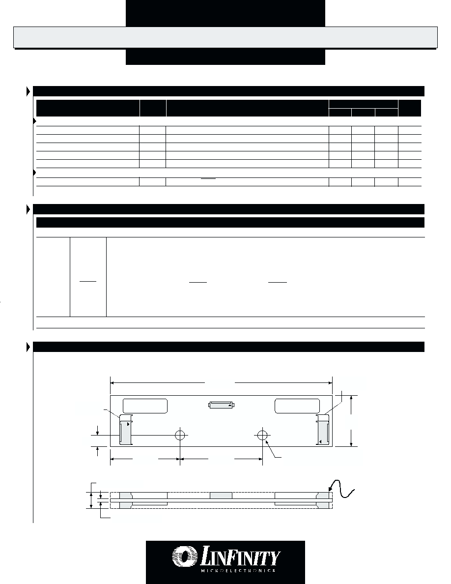
P H Y S I C A L D I M E N S I O N S
4.88 (124)
1.26
(32)
0.060 (1.52) max.
0.338 (8.6) Max.
Warning!!
High Voltage Present
At All Output
Connectors
0.24 (6)
Ø 0.12 (3.0)
Grounded Mounting Hole - 2 plcs
1.50 (38)
1.89 (48)
CN2
(Bottom Side)
CN3
(Bottom Side)
CN1
CN4
CN5
LXM1621-xx
All dimensions are in inches (mm)
D
IGITAL
D
IMMING
D
UAL
L
AMP
CCFL I
NVERTER
M
ODULE
LXM1621-xx
P R O D U C T D A T A B O O K 1 9 9 6 / 1 9 9 7
Copyright © 2000
Rev. 0.6 2/00
4
P
R E L I M I N A R Y
D
A T A
S
H E E T
P
A T E N T
P
E N D I N G
RangeMAX
TM
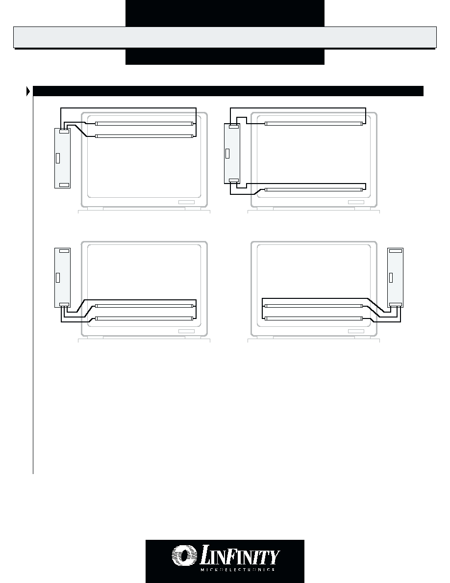
T Y P I C A L C O N N E C T I O N C O N F I G U R AT I O N S
LXM
1
621-xx
CCFL Lamps
Desktop Display
CCFL Lamps
LXM
1
621-xx
Desktop Display
CCFL Lamps
Desktop Display
LXM
1
621-xx*
CCFL Lamps
Desktop Display
CN5
CN4
CN1
CN5
CN4
CN1
CN1
CN2
CN3
*
Connectors CN2 and CN3 are on the bottom side of the inverter. View shown is looking through the board.
LXM
1
621-xx
CN5
CN4
CN1
These examples illustrate four typical LCD wiring configurations
that are accomodated by Linfinity's unique connector array.
Linfinity inverters have multiple lamp connector styles that are
common to the industry, which are duplicated at both ends of the
module. This permits over 12 variations of module mounting and
interconnectivity configurations.
FIGURE 1 -- Connectivity Configuration Examples
D
IGITAL
D
IMMING
D
UAL
L
AMP
CCFL I
NVERTER
M
ODULE
LXM1621-xx
P R O D U C T D A T A B O O K 1 9 9 6 / 1 9 9 7
5
Copyright © 2000
Rev. 0.6 2/00
P
R E L I M I N A R Y
D
A T A
S
H E E T
P
A T E N T
P
E N D I N G
RangeMAX
TM
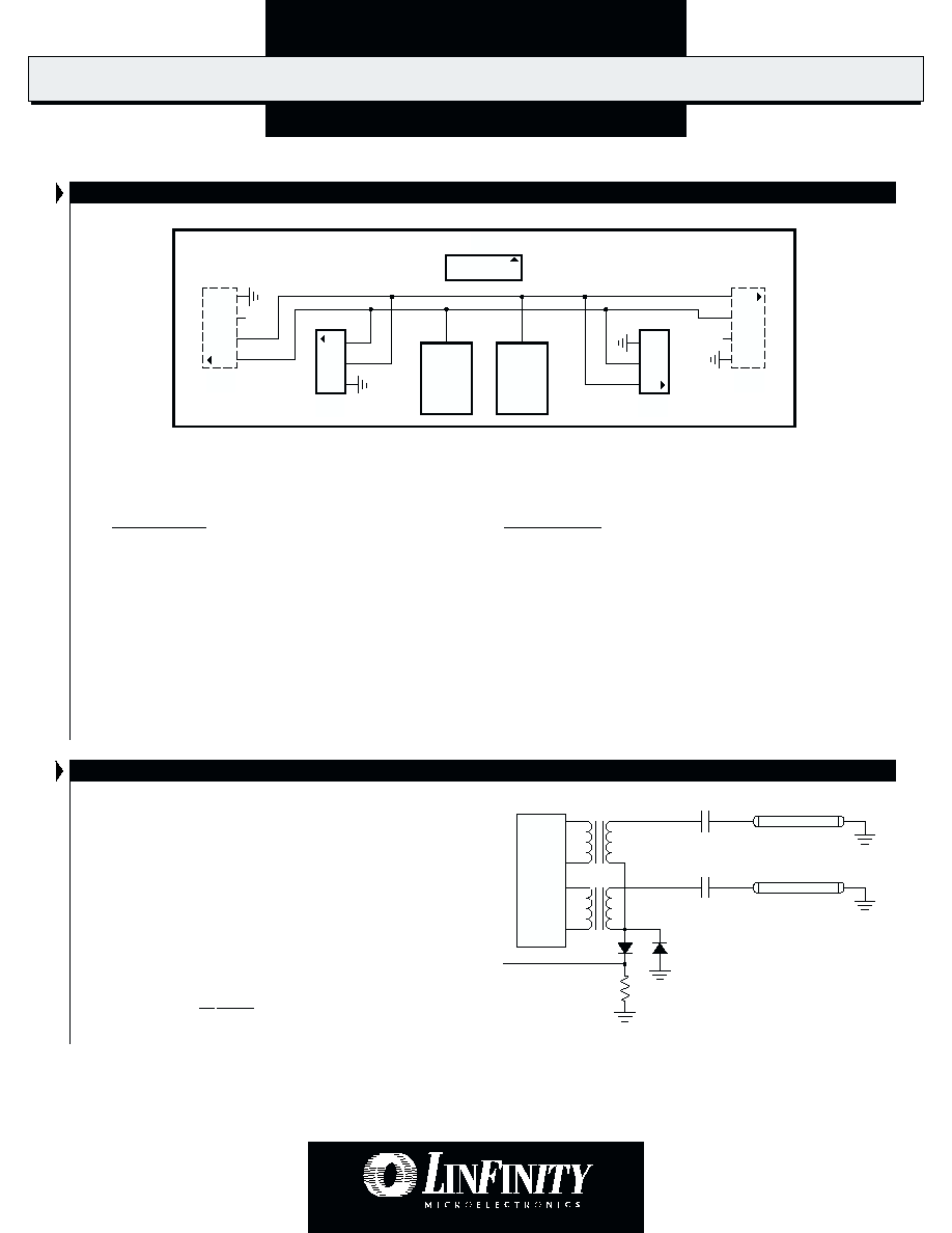
C O N N E C T O R S C H E M A T I C
CN2
CN3
CN1
4
3
2
1
1
2
3
CN4
N.C.
3
2
1
CN5
1
2
3
4
N.C.
Inverter
Output 1
Inverter
Output 2
8
1
V
HI2
V
HI1
FIGURE 2 -- LXM1621-xx Connector Schematic
Note: CN2 and CN3 (shown with dashed lines) are located on the opposite side of the PCB from CN1, CN4
and CN5. Their pin numbers are shown as viewed looking through the printed circuit board.
Connectors:
Mates With:
CN1
= MOLEX 53261-0890
Pins: 50079-8100*, Housing: 51021-0800
*
Loose (-8000, Chain) Recommended #26 AWG wiring
CN2, CN3
= JST SM04(4.0)B-BHS-1-TB
JST BHR-04VS-1
CN4, CN5
= JST SM03(4.0)B-BHS-1-TB
JST BHR-03VS-1
Connection Rules
1. Always install two (2) lamps. Operating with only one lamp may overdrive lamp current at maximum brightness settings.
2. Verify lamp wiring before connecting lamps to the inverter module. Connecting both lamps to one of the two inverter output circuits
will result in reduced brightness. The LXM1621-xx module connectors are wired per industry standard. The lamp hot wires (high voltage wires)
are always on pin 1 or 2, and the cold wire (low voltage wire) is always on pin 3 or 4.
F A I L S A F E F E AT U R E F O R M U L T I P L E L A M P O P E R A T I O N S
Our multi-output inverters are designed to keep your application
operating at near normal brightness in the event that a lamp fails.
This allows the display to remain "on-line" until lamp replacement
is convenient.
Linfinity "pairs" the lamps so that if one lamp in the pair breaks,
most of its current is added to the good lamp. CCFLs will respond
with more brightness for a period of time. Operating time in this
mode will be a function of the lamps age but should be typically
in the order of hundreds of hours.
This operating characteristic can provide adequate display
performance for a limited, but useful period of time. Shortening
of the lamp life in this mode is typically not a concern as it is
recommended that all lamps in a display be replaced at the same
time.
FIGURE 3 -- Dual Output Stage
I
S
Lamps