MSCOXXXA 12-14-98 DSW UM2300 <->(34989)
UM2300
SERIES
Features
∑
LF band (100 KHz) PIN
∑
Long Lifetime (80
µ
s typ.)
∑
High Power (1 KW CW)
∑
High Isolation (35 dB)
∑
Low Loss (0.2 dB)
∑
Very Low Distortion (IP3 = > 60 dBm)
∑
Voltage Ratings to 1000 V
Description
Electrical Specifications (25
∞
C)
Test
Min.
Typ.
Max.
Units
Conditions
Diode Resistance R
S
0.3
0.4
F
1
= 1 MHz, 100 mA
Capacitance C
T
15
20
pF
F
2
= 1 MHz, 100 V
Reverse Current I
R
10
µ
A
@ Rated Voltage
Carrier Lifetime
60
80
µ
s
I
f
= 10 mA / 100 V
IP3
50
60
dBm
2 WATT total, I
f
= 25 mA
F
1
= 0.999 MHz, F
2
= 1.001 MHz
1.0 WATT/ tone
Thermal Resistance
1.0
∞
C / W
25
∞
C Stud Temperature
0
20
40
60
80
100
120
140
160
180
200
Vr (VOLTS)
0
10
20
30
40
50
60
70
80
90
100
110
120
130
Ct (pF)
TYPICAL CAPACITANCE vs REVERSE VOLTAGE
4 MHz
2 MHz
1 MHz
400 KHz
200 KHz
100 KHz
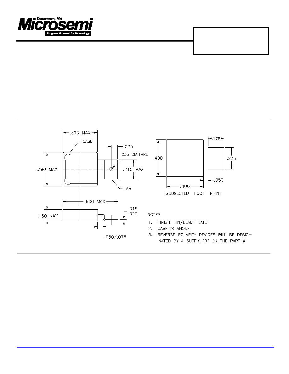
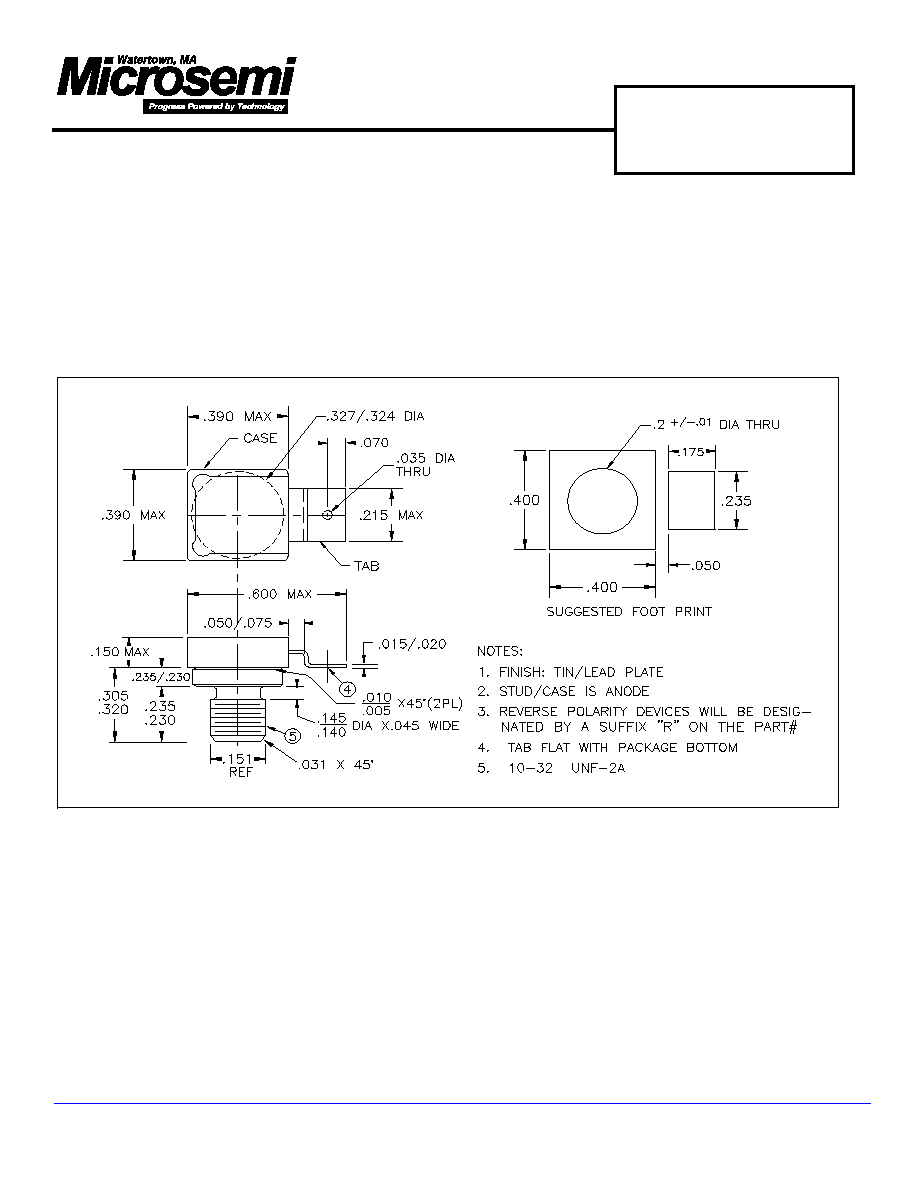
580 Pleasant St.
Watertown, MA 02472
PH: (617) 926-0404
FAX: (617) 924-1235
PIN DIODE
SWITCH
UM2300 Series PIN diodes are designed for transmit /
receive switch and attenuator application in LF band
( 100 KHz ) and above. As series configured switches,
these long lifetime (80
µ
S typ) diodes can control up to
2.5 KW CW in a 50 ohm system. In MF band, insertion
loss is less than 0.2 dB and isolation is greater than
35 dB (`off
'state).
The UM2300 series offers the lowest distortion perform-
ance in both transmit & receive modes. Less than 10
mA forward bias is required to obtain an IP3 of 60 dBm
at 150 KHz with 1 watt per tone. The forward biased
resistance/reactance vs. frequency characteristics are
flat down to 10 KHz. Capacitance vs. reverse bias volt-
age characteristic is flat down to 1 MHz.
In attenuator configurations, the UM2300 produces
extremely low distortion at low values of attenuator
control current, & very low insertion loss ( 0.2 dB) in
the ` 0 dB ' attenuator state.
Reverse Voltage ( V
R
) DEVICE
@ I
R
= 10
µ
A
100 VOLTS............ UM2301
200 VOLTS............ UM2302
400 VOLTS............ UM2304
600 VOLTS............ UM2306
800 VOLTS............ UM2308
1000
VOLTS............
UM2310
Voltage Ratings (25
∞
C)
MSCOXXXA 12-14-98 DSW UM2300 <->(34989)
UM2300
SERIES
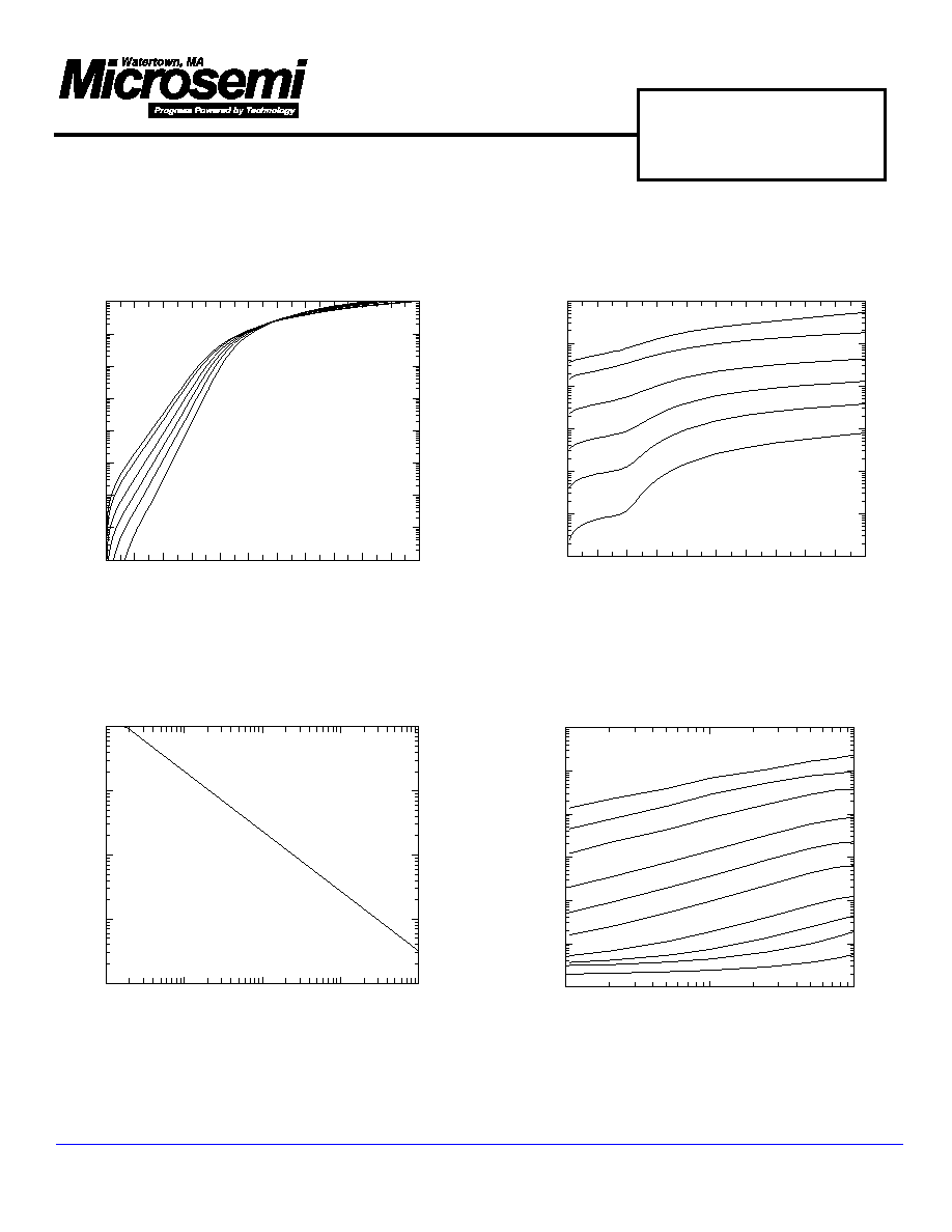
0
100 200 300 400 500 600 700 800 900 1000
VR (Volts)
-8
10
-7
10
-6
10
-5
10
-4
10
-3
10
-2
10
IR (A) (MEAN)
TYPICAL IR vs VR
150 oC
125 oC
100 oC
75 oC
50 oC
25 oC
0.0 0.2 0.4 0.6 0.8 1.0 1.2 1.4 1.6 1.8 2.0 2.2
Vf [VOLTS]
-6
10
-5
10
-4
10
-3
10
-2
10
-1
10
0
10
1
10
2
10
If [AMPERES]
TYPICAL I-V CURVE
150 oC
125 oC
100 oC
75 oC
50 oC
25 oC
.01
.1
1
10
100
If (mA)
.1
1
10
100
1000
Rs (Ohms)
TYPICAL RS vs FORWARD BIAS CURRENT
0
10
1
10
2
10
REVERSE VOLTAGE (VOLTS)
3
10
4
10
5
10
6
10
7
10
8
10
9
10
Rp (OHMS)
TYPICAL Rp vs REVERSE VOLTAGE
10KHz
20KHz
40KHz
100KHz
200KHz
400KHz
1MHz
2MHz
4MHz
10MHz

MSCOXXXA 12-14-98 DSW UM2300 <->(34989)
UM2300
SERIES
-3
10
-2
10
-1
10
0
10
1
10
If [AMPERES]
-3.0
-2.5
-2.0
-1.5
-1.0
-0.5
0.0
TCVf [mV/oC]
TYPICAL TCVf vs If
125 oC
DELTA
1
10
100
1000
Pt - PULSE TIME - (ms)
.01
.1
1
10
THERMAL IMPEDANCE - (C/W)
TYPICAL THERMAL IMPEDANCE
With Heatsink
No Heatsink
1
10
2
3
4
5
6
7 8
If NEEDED TO OBTAIN AN IM3 OF - 60 dBc (mA)
15
20
25
30
35
40
POWER LEVEL/TONE (dBm)
45
50
55
60
65
70
IP3 (dBm)
TYPICAL POWER LEVEL vs FORWARD BIAS CURRENT
500KHz 250KHz 150KHz
TAU = 0.1 ms
f1 = F +/- 1 KHz
f2 = F +/- 1 KHz