Microsemi
Scottsdale Division
8700 E. Thomas Rd. PO Box 1390, Scottsdale, AZ 85252 USA, (480) 941-6300, Fax: (480) 947-1503
Page 1
Copyright
©
2002
5-08-2003 REV 0
WWW.
Microsemi
.
COM
UMAF5.0A thru UMAF170CA
U
LTRA
M
ITETM SURFACE MOUNT 500 Watt
Transient Voltage Suppressor 5.0 to 170 V
S C O T T S D A L E
D I V I S I O N
UMAF5.0A thru
UMAF170CA
E
NVIRONMENTALLY
L
EAD
-F
REE
DESCRIPTION
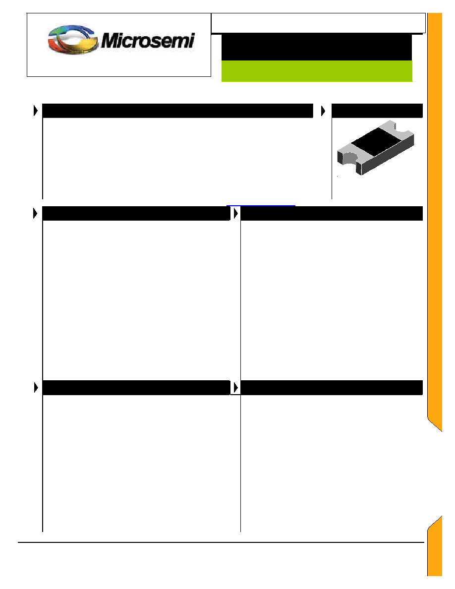
PACKAGE
These 500 watt transient voltage suppressors offer power-handling capabilities only
found in larger packages. They are also environmentally Lead-Free both externally
and internally. They are used for protecting against a variety of transients from
inductive switching environments or lower levels of induced secondary lightning effects
of IEC61000-4-5.
It offers the same size footprint as the popular DO-214AC or
BA package outlines except with a much lower profile height. Its robust
configuration in a "2010" style MELF package prevents damage to extended-
lead terminals and virtually eliminates inductive parasitics from fast rise-time
transients with very short internal/external conduction paths. They a
re also very
effective in protection from ESD or EFT per IEC61000-4-2 and IEC61000-4-4.
UltraMite
IMPORTANT: For the most current data, consult MICROSEMI's website:
http://www.microsemi.com
FEATURES
APPLICATIONS / BENEFITS
∑
Available as a unidirectional or bidirectional device
(bidirectional with CA suffix)
∑
Fast response time
∑
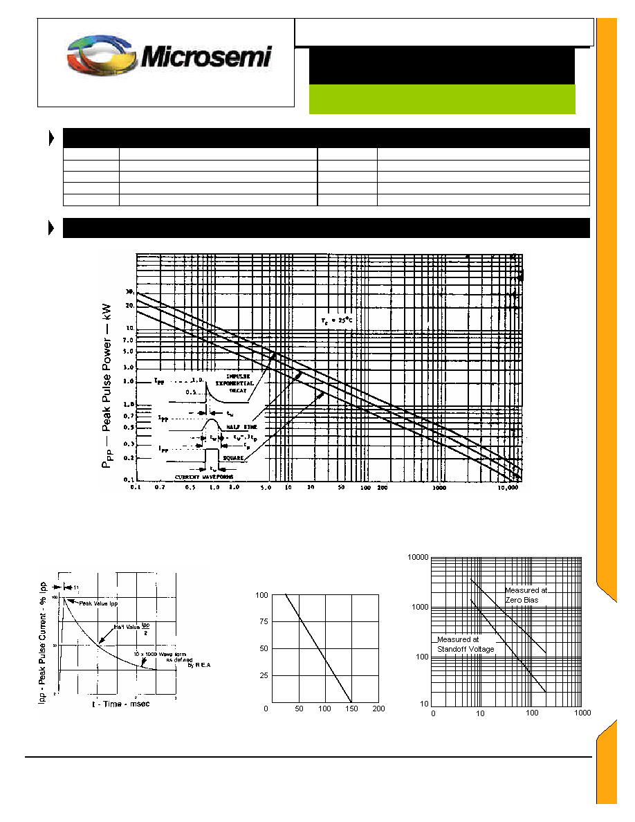
Suppresses transients up to 500 W @ 10/1000 µs (see
Figure 1, 2, and 3).
∑
Robust 2010 MELF style flat package configuration for
accurate pick-and-place handling
∑
Fits same small narrow PCB pad layouts as "SMAJ"
packages in JEDEC DO-214AC (or BA)
∑
Very low height profile (approx 1 mm)
∑
Available on Tape and Reel
∑
Built-in stress relief with similar COE as PC boards
∑
Lead-Free construction externally and internally
∑
Optional Lead-Tin finish (UMA5.0A-170CA)
∑
Options for screening in accordance with MIL-PRF-
19500 for JAN, JANTX, JANTXV, and JANS are
available by adding MQ, MX, MV, or MSP prefixes
respectively to part numbers
∑
Protects sensitive components such as IC's, CMOS,
Bipolar, BiCMOS, ECL, DTL, T
2
L, etc.
∑
Protection from switching transients & induced RF
∑
Compliant to IEC61000-4-2 and IEC61000-4-4 for ESD
and EFT protection respectively
∑
Secondary lightning protection per IEC61000-4-5 with
42 Ohms source impedance:
Class 1: UMAF5.0 to UMAF100A or CA
Class 2: UMAF5.0 to UMAF51A or CA
Class 3: UMAF5.0 to UMAF24A or CA
Class 4: UMAF5.0 to UMAF12A or CA
ß
Secondary lightning protection per IEC61000-4-5 with
12 Ohms source impedance:
Class 1: UMAF5.0 to UMAF30A or CA
Class 2: UMAF5.0 to UMAF16A or CA
ß
Virtually zero inductive parasitics with minimal Ldi/dt
voltage overshoots for fast-rise-time transients
MAXIMUM RATINGS
MECHANICAL AND PACKAGING
∑
Peak Pulse Power dissipation at 25
∫
C: 500 watts at
10/1000 µs (also see Fig 1, 2, and 3)
∑
Impulse repetition rate (duty factor): 0.01%
∑
t
clamping
(0 volts to
V
(BR)
min.): < 100 ps theoretical for
unidirectional and < 5 ns for bidirectional
∑
Operating and Storage temperature: -55
∫
C to +150
∫
C
∑
Thermal resistance: 50
∫
C/W junction to lead, or
115
∫
C/W junction to ambient when mounted on FR4
PC board (1oz Cu) with recommended 5 mm
2
pads
(see last page)
∑
Steady-State Power: 2.5 watts at T
L
= 25
o
C, or 1.08
watts at T
A
= 25
∫
C when mounted on FR4 PC board
with recommended 5 mm
2
footprint pads
∑
Forward Surge Current at 25∫C: 40 amps peak, 8.3
ms half-sine wave. Maximum voltage of 3.50 V
(unidirectional only)
∑
FRP substrate material and epoxy under-fill package
meeting UL94V-0
∑
Terminals Tin plated (solderable per MIL-STD-750,
Method 2026)
∑
Body marked with part number without UMA prefix
(e.g. F05, F15A, F33A, F58, F150CA, etc.)
∑
Cathode designated with band (no band on
bidirectional)
∑
Weight: 0.020 grams (approx)
∑
Tape & Reel packaging per EIA-481-2 with 12 mm
tape and 3000 units/reel (7 inch) or 10,000 units/reel
(13 inch)
∑
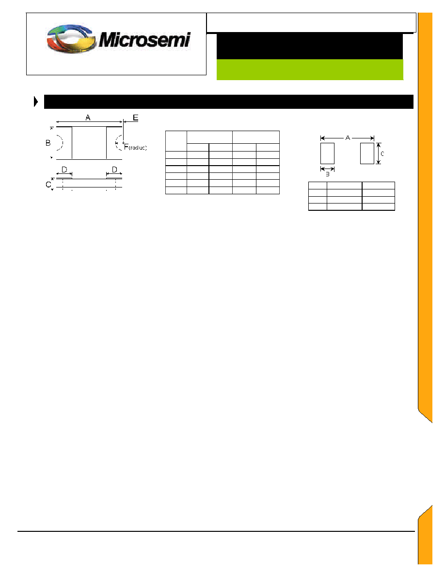
See package dimensions on last page

Microsemi
Scottsdale Division
8700 E. Thomas Rd. PO Box 1390, Scottsdale, AZ 85252 USA, (480) 941-6300, Fax: (480) 947-1503
Page 2
Copyright
©
2002
5-08-2003 REV 0
WWW.
Microsemi
.
COM
UMAF5.0A thru UMAF170CA
U
LTRA
M
ITETM SURFACE MOUNT 500 Watt
Transient Voltage Suppressor 5.0 to 170 V
S C O T T S D A L E
D I V I S I O N
UMAF5.0A thru
UMAF170CA
E
NVIRONMENTALLY
L
EAD
-F
REE
ELECTRICAL CHARACTERISTICS @25
o
C
Microsemi
Part NUMBER*
RATED
WORKING
PEAK
STANDOFF
VOLTAGE
V
WM
(V)
BREAKDOWN
VOLTAGE
V
(BR)
MIN
@
I
(BR)
(V)
BREAKDOWN
CURRENT
I
(BR)
(mA)
MAXIMUM
CLAMPING
VOLTAGE
V
C
@ I
PP
(V)
PEAK
PULSE
CURRENT
I
PP
(A)
MAXIMUM
STANDBY
CURRENT
I
D
@ V
WM
(
µ
A)
UMAF5.0A
UMAF6.0A
UMAF6.5A
UMAF7.0A
5.0
6.0
6.5
7.0
6.40
6.67
7.22
7.78
10
10
10
10
9.2
10.3
11.2
12.0
54.3
48.5
44.7
41.7
800
800
500
200
UMAF7.5A
UMAF8.0A
UMAF8.5A
UMAF9.0A
7.5
8.0
8.5
9.0
8.33
8.89
9.44
10.0
1
1
1
1
12.9
13.6
14.4
15.4
38.8
36.7
34.7
32.6
100
50
10
5
UMAF10A
UMAF11A
UMAF12A
UMAF13A
10
11
12
13
11.1
12.2
13.3
14.4
1
1
1
1
17.0
18.2
19.9
21.5
29.4
27.4
25.1
23.2
5
5
5
5
UMAF14A
UMAF15A
UMAF16A
UMAF17A
14
15
16
17
15.6
16.7
17.8
18.9
1
1
1
1
23.2
24.4
26.0
27.6
21.5
20.6
19.2
18.1
5
5
5
5
UMAF18A
UMAF20A
UMAF22A
UMAF24A
18
20
22
24
20.0
22.2
24.4
26.7
1
1
1
1
29.2
32.4
35.5
38.9
17.2
15.4
14.1
12.8
5
5
5
5
UMAF26A
UMAF28A
UMAF30A
UMAF33A
26
28
30
33
28.9
31.1
33.3
36.7
1
1
1
1
42.1
45.4
48.4
53.3
11.9
11.0
10.3
9.4
5
5
5
5
UMAF36A
UMAF40A
UMAF43A
UMAF45A
36
40
43
45
40.0
44.4
47.8
50.0
1
1
1
1
58.1
64.5
69.4
72.7
8.6
7.8
7.2
6.9
5
5
5
5
UMAF48A
UMAF51A
UMAF54A
UMAF58A
48
51
54
58
53.3
56.7
60.0
64.4
1
1
1
1
77.4
82.4
87.1
93.6
6.5
6.1
5.7
5.3
5
5
5
5
UMAF60A
UMAF64A
UMAF70A
UMAF75A
60
64
70
75
66.7
71.1
77.8
83.3
1
1
1
1
96.8
103.0
113
121
5.2
4.9
4.4
4.1
5
5
5
5
UMAF78A
UMAF85A
UMAF90A
UMAF100A
78
85
90
100
86.7
94.4
100
111
1
1
1
1
126
137
146
162
4.0
3.6
3.4
3.1
5
5
5
5
UMAF110A
UMAF120A
UMAF130A
UMAF150A
110
120
130
150
122
133
144
167
1
1
1
1
177
193
209
243
2.8
2.6
2.4
2.1
5
5
5
5
UMAF160A
UMAF170A
160
170
178
189
1
1
259
275
1.9
1.8
5
5
* Order with "CA" suffix for bi-directional types. Capacitance will be Ω that shown in figure 4.