
P
P
R
R
E
E
L
L
I
I
M
M
I
I
N
N
A
A
R
R
Y
Y
Microsemi
580 Pleasant Street, Watertown, MA. 02472-2408, 617-926-0404, Fax: 617-924-1235
Page 1
Copyright
2002
Rev. 2., 2003-06-03
WWW
.
Microse
m
i
.
CO
M
UPBLEDLPxx
HIGH BRIGHTNESS BLUE LED
P
RODUCT
P
REVIEW
The UPBLEDLPxx blue LED product series incorporates Microsemi's unique,
low profile packaging concept. Ideally suited for high density circuitry used in a
variety of telecommunication lighting applications. The product offers robust
packaging, and low forward voltage for high efficiency as well as modest
junction temperature rise.
IMPORTANT: For the most current data, consult MICROSEMI's website: http://www.microsemi.com
For operation of these LEDs in pulse mode applications, devices may be used in conjunction with
the Microsemi LX1992LED Drivers
ABSOLUTE MAXIMUM RATINGS AT 25∫ C
(UNLESS OTHERWISE SPECIFIED)
THERMAL CHARACTERISTICS
( U N L E S S O T H E R W I S E S P E C I F I E D )
Thermal Response
Symbol
Value Units
Junction Temperature rise at 20ma dc
TJ
mx
15
∞C
The first "x" of the postscript designates the Intensity bin , i.e. H highest, G lower, F lowest
The second "x" of the postscript designates the forward voltage category L, lowest, S, Standard
See pg. 2 for details.
Parameters Symbol
Value
Unit
DC
Forward Drive Current
I
F
30
mA
Peak Forward Current
I
FP
100 mA
LED Operating Junction Temperature
Tj
-40 to +140
∞C
Reverse Voltage
V
R
8 V
Power Dissipation
P
D
125
mW
Operating Temperature
T
OPR
-40 to +125
∞C
Storage Temperature
T
S
-45 to +140
∞C
Electrostatic Discharge
ESD
1000
V
ESD classification
Class 1
Solder Reflow Peak Temperature (Solder 10")
225
∞C
K E Y F E A T U R E S
Low profile (0.35mm;15mils)
Low Vf available (<3.0V @5mA)
Wide viewing angle
High brightness
Luminous Efficiency
Rugged Optomite package
APPLICATIONS/BENEFITS
Mobile Phone Keypad
Panel, button, switch indicators.
Backlighting
Signage
Signals and Marker Lights
U
U
P
P
B
B
L
L
E
E
D
D
L
L
P
P
X
X
X
X
P
P
R
R
E
E
L
L
I
I
M
M
I
I
N
N
A
A
R
R
Y
Y
Microsemi
580 Pleasant Street, Watertown, MA. 02472-2408, 617-926-0404, Fax: 617-924-1235
Page 2
Copyright
2002
Rev. 2., 2003-06-03
WWW
.
Microse
m
i
.
CO
M
UPBLEDLPxx
HIGH BRIGHTNESS BLUE LED
P
RODUCT
P
REVIEW
∑
Change in Radiant Intensity with temperature ≠1.4µW/sr/∞C (25∞C < temp< 85∞C)
∑
Change in Radiant Intensity with temperature 0.7µW/sr/∞C (25∞C < temp< -40∞C)
ELECTRICAL PARAMETERS @ 25∞C & ID=20 mA (unless otherwise specified)
Characteristic Symbol
Test
Conditions Min
Typ.
Max
Units
Radiant Intensity
I
E
"F" DC Drive Current = 20ma
"G" DC Drive Current = 20ma
"H" DC Drive Current = 20ma
550
750
900
µW/sr
Luminous Intensity
I
V
"F" DC Drive Current = 20ma
"G" DC Drive Current = 20ma
"H" DC Drive Current = 20ma
35
45
55
mcd
Dominant Wavelength
DOM
DC Drive Current = 20ma
460
480
nm
Peak Wavelength
PK
DC Drive Current = 20ma
465
nm
Chrom x
Chrom y
"F", "G", "H"
DC Drive Current = 20ma
0.13
0.07
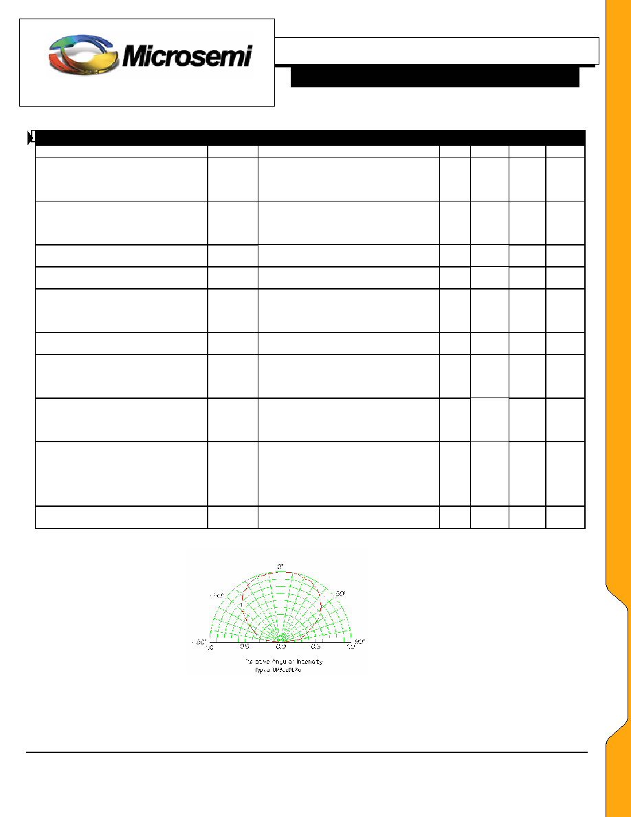
Angle Coverage to 50% points
1/2
DC Drive Current = 20ma to 50ma
125
135
deg.
Radiant Flux
E
"F" DC Drive Current = 20ma
"G" DC Drive Current = 20ma
"H" DC Drive Current = 20ma
1.25
1.75
2.0
mW
Luminous Flux
V
"F" DC Drive Current = 20ma
"G" DC Drive Current = 20ma
"H" DC Drive Current = 20ma
125
150
175
mlm
Forward Voltage
V
F
"S" DC Drive Current 5ma
"L" DC Drive Current 5ma
"S" DC Drive Current 10ma
"L" DC Drive Current 10ma
"S" DC Drive Current 20ma
"L" DC Drive Current 20ma
3.4
2.95
3.5
3.0
3.7
3.15
3.5
3.05
3.7
3.125
3.9
3.25
V
Reverse Leakage Current
I
R
Reverse Voltage = 5 V
10 µA
Forward Voltage
V
F
3.9 V
U
U
P
P
B
B
L
L
E
E
D
D
L
L
P
P
X
X
X
X

P
P
R
R
E
E
L
L
I
I
M
M
I
I
N
N
A
A
R
R
Y
Y
Microsemi
580 Pleasant Street, Watertown, MA. 02472-2408, 617-926-0404, Fax: 617-924-1235
Page 3
Copyright
2002
Rev. 2., 2003-06-03
WWW
.
Microse
m
i
.
CO
M
UPBLEDLPxx
HIGH BRIGHTNESS BLUE LED
P
RODUCT
P
REVIEW
Notes: Anode is identified by observing the underside of the LED.
(Anode is the smaller of the two base pads)
Mount to circuit board using 60/40 Pb/Sn or equivalent.
Maximum solder melt exposure temperature is 225∞C for 10 seconds.
TAPE AND REEL
3,000 units/reel Notes: Dimensions is shown in metric.
UP
BLEDLPxx

P
P
R
R
E
E
L
L
I
I
M
M
I
I
N
N
A
A
R
R
Y
Y
Microsemi
580 Pleasant Street, Watertown, MA. 02472-2408, 617-926-0404, Fax: 617-924-1235
Page 4
Copyright
2002
Rev. 2., 2003-06-03
WWW
.
Microse
m
i
.
CO
M
UPBLEDLPxx
HIGH BRIGHTNESS BLUE LED
P
RODUCT
P
REVIEW
Mounting footprint, Copper (note: Silver plating will enhance Luminous Intensity)
JUNCTION TEMPERATURE RISE
5
10
15
20
25
30
35
40
45
50
0
10
20
30
40
dc drive current (ma)
Junction temper
atur
e r
i
se (
∞
C)
T
T
H
H
E
E
R
R
M
M
A
A
L
L

P
P
R
R
E
E
L
L
I
I
M
M
I
I
N
N
A
A
R
R
Y
Y
Microsemi
580 Pleasant Street, Watertown, MA. 02472-2408, 617-926-0404, Fax: 617-924-1235
Page 5
Copyright
2002
Rev. 2., 2003-06-03
WWW
.
Microse
m
i
.
CO
M
UPBLEDLPxx
HIGH BRIGHTNESS BLUE LED
P
RODUCT
P
REVIEW
2.75
3
3.25 3.5 3.75
4
4.25
0
20
40
60
Forward Voltage (V)
dc Drive Current (mA)
L S
0
25
50
75
100 125 150
0
20
40
60
Luminous Intensity (mcd)
dc Drive Current (mA)
F G H
0
1000
2000
0
20
40
60
Radiant Intensity (µW/sr)
dc Drive Current (mA)
0
0.1
0.2
0.3
0.4
0
20
40
60
Luminous Flux (Lumens)
dc Drive Current (mA)
F G H
F G H
chrom y chrom x
0.06
0.08
0.1
0.12
0.14
0
10
20
30
40
50
Chrom x and y
dc Drive Current (mA)