
MSC 02-17-00
PRELIMINARY
UPFS320P
Features
∑
POWERMITE 3 Surface Mount Package
∑
MOSFET with Schottky Rectifier for reverse voltage blocking
∑
Single 3 leaded device replaces 2 individual components
∑
Integral Heat Sink / Locking Tabs
∑
Supplied in 16mm Tape and Reel ≠ 6000 units/reel
∑
Superior Low Thermal and Electrical capability
Mechanical Characteristics
∑
Footprint Area of 16.51 mm
2
∑
Case: Molded Epoxy
∑
Meets UL94VO at 1/8 inch
∑
Weight: 72 milligrams
∑
Lead and Mounting Temperatures: 260
∞
∞
∞
∞
C max for 10 seconds
Description
Note: Vks = Vds (Mosfet) + Vf (Rectifier)
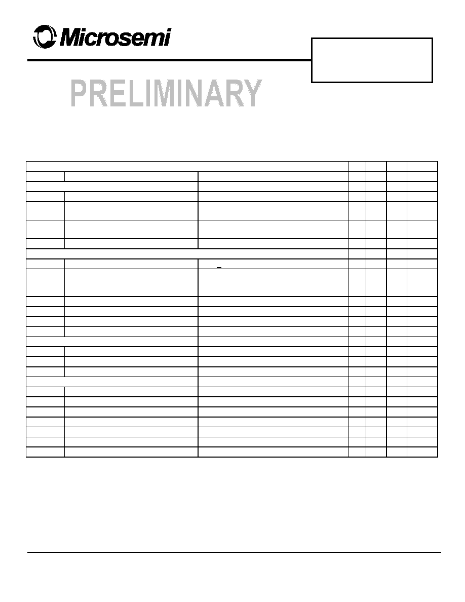
Absolute Maximum Ratings at 25
∞
C
RATING SYMBOL VALUE
UNIT
Cathode-to-Source Voltage VKSS +/- 20
Vdc
Gate-to-Source Voltage VGS +/- 8 Vdc
Cathode Current:
Continuous @ TA=25
∞
∞
∞
∞
C
IK 3.0 Adc
Single Pulsed IKM 11.0
Apk
Total Power Dissipation PD (1)
2.0 Watts
Storage Temperature T stg
-55 to 150
∞
∞
∞
∞
C C
Operating Temperature
T op -55 to 150
∞
∞
∞
∞
C C
Thermal Characteristics
Thermal Resistance:
Junction to Tab Rjtab 5
∞
∞
∞
∞
C/Watt
(1)Junction-to-tab Rja (1) 60
∞
∞
∞
∞
C/Watt
(2)Junction-to-ambient Rja (2) 120
∞
∞
∞
∞
C/Watt
(1) Mounted on 2" square by 0.06' thick FR4 board with a 1" x1" square 2 ounce copper pattern.
(2) Mounted on 0.06 thick FR4 board, using recommended footprint, with 2 ounce copper
# 580 Pleasant Street
Watertown, MA 02472
Phone:(617) 926-0404
F A X : (617) 924-1235
SURFACE MOUNT
P ≠ CHANNEL
MOSKEY
The MOSKEY
combines a MOSFET with a Schottky Recti-
fier to provide reverse blocking capability in a single three
leaded package. This device is well suited for applications
such as battery chargers and switching where the intrinsic
source-drain diode is an undesirable feature.
MSC 02-17-00
PRELIMINARY
UPFS320P
Electrical Characteristics at 25
∞
C
ELECTRICAL CHARACTERISTICS (TA = 25 C unless otherwise noted)
Symbol
Parameter
Conditions
Min Typ Max
Units
OFF CHARACTERISTICS
BVKSS
Cathode-Source Breakdown Voltage VGS= 0V; IK = 250uA
20
V
IKSSF
Zero Gate Voltage Cathode Current:
Forward
VKS= -16V, VGS = 0V
1
uA
IKSSR
Zero Gate Voltage Cathode
Current:Reverse
VKS= +16V, VGS = 0V
1.5
mA
IGSS
Gate-Body Leakage Current
VGS= +/- 8V, VDS = 0V
100
nA
ON CHARACTERISTICS (pulsed 500us max, duty cycle < 2%)
VGS(TH)
Gate Threshold Voltage
VDS > VGS; IK = 250uA
0.4
0.6
1
V
DELTA
VGS(TH)/
TJ
Gate Threshold Voltage Temp
Coefficient
IK = 250uA, Reference to 25C
2.1
mV/C
VKS (ON) Static Cathode-Source On Voltage
VGS = 4.5 V; IK = 3A
700
mV
VKS (ON) Static Cathode-Source On Voltage
VGS = 4.5 ; IK = 1A
400
mV
IK(ON)
On State Cathode Current
VGS = 4.5 V; VKS = 5V
10
A
Gfs
Forward Transconductance
VDS = 10 V; IK = 3 A
6.5
S
DYNAMIC CHARACTERISTICS
Ciss
Input Capacitance
VKS = 10 V; VGS = 0V, F = 1MHz
700
pF
Coss
Output Capacitance
VKS = 10 V; VGS = 0V, F = 1MHz
270
pF
Crss
Reverse Transfer Capacitance
VKS = 10 V; VGS = 0V, F = 1MHz
100
pF
SWITCHING CHARACTERISTICS
Td
(ON)
Turn On Delay Time
VDD = 5V, IK = 1A, VGS = 4.5V, Rg = 6
8
16
ns
Tr
Turn On Rise Time
VDD = 5V, IK = 1A, VGS = 4.5V, Rg = 6
24
38
ns
Td
(OFF)
Turn Off Delay time
VDD = 5V, IK = 1A, VGS = 4.5V, Rg = 6
50
80
ns
Tf
Turn Off Fall time
VDD = 5V, IK = 1A, VGS = 4.5V, Rg = 6
29
45
ns
Qg
Total Gate Charge
VDS = 5V, IK = 3A, VGS = 4.5V
9.5
13
nC
Qgs
Gate-Source Charge
VDS = 5V, IK = 3A, VGS = 4.5V
1.3
nC
Qgd
Gate-Cathode Charge
VDS = 5V, IK = 3A, VGS = 4.5V
2.2
nC


