MIK9278F
8 Digit Calculator IC
February 2002
Description
The MIK9278F is a single-chip LSI CMOS calculator with 8-digit four function arithmetic operations, single memory, extraction of square
root and percentage calculation functions, leading zero and trailing zero suppression, chain calculations and internal debunking and
encoding of keyboard inputs. It is designed for LCD operation with 1.5 V power supply (either from solar cell or battery), auto-power off,
low power dissipation and single power supply making the MIK9278F ideal for hand held calculators with low system cost.
Features
╖ Number of digits 8 digits (rough estimated calculation is
possible).
╖ Calculations:
¡ Standard four functions (+, -, x, /).
¡ Chain multiplication and division.
¡ Auto¡constant calculation (constant multiplicand,
divisor, addend and subtrahend).
¡ Square and reciprocal calculations.
¡ mark¡up and mark¡down calculations.
¡ Extraction of square root.
¡ Percentage calculations.
¡ Power calculations.
¡ Rough estimate calculations.
¡ Memory calculations.
╖ Decimal point system¡complete floating decimal point
system.
╖ Display format: 8 digits + sign (¡, E & M) leading zero
suppression zero shift.
╖ Negative number indication: number + minus (-) sign.
╖ Auto power off ability.
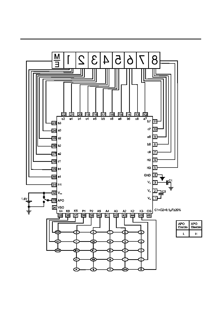
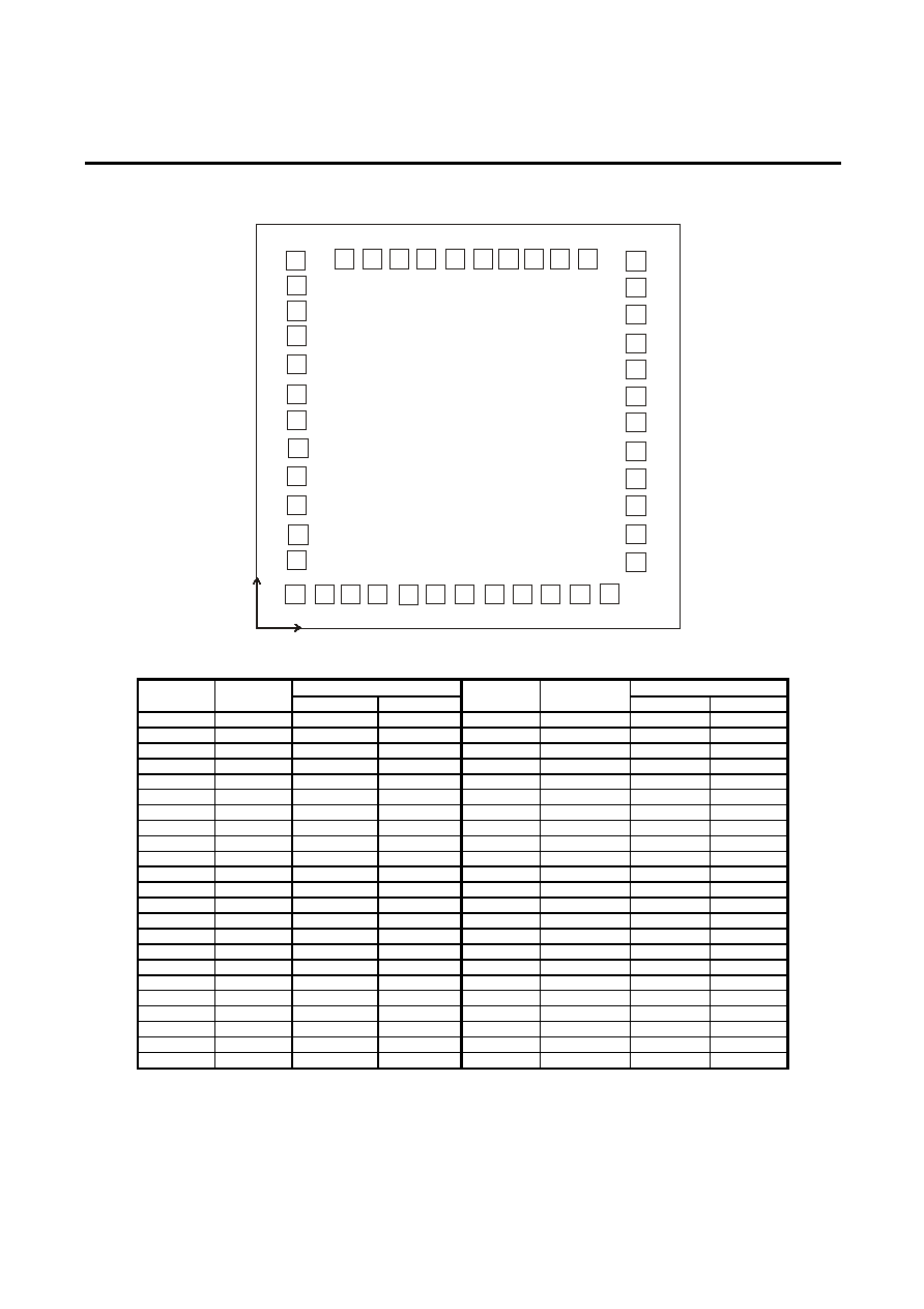
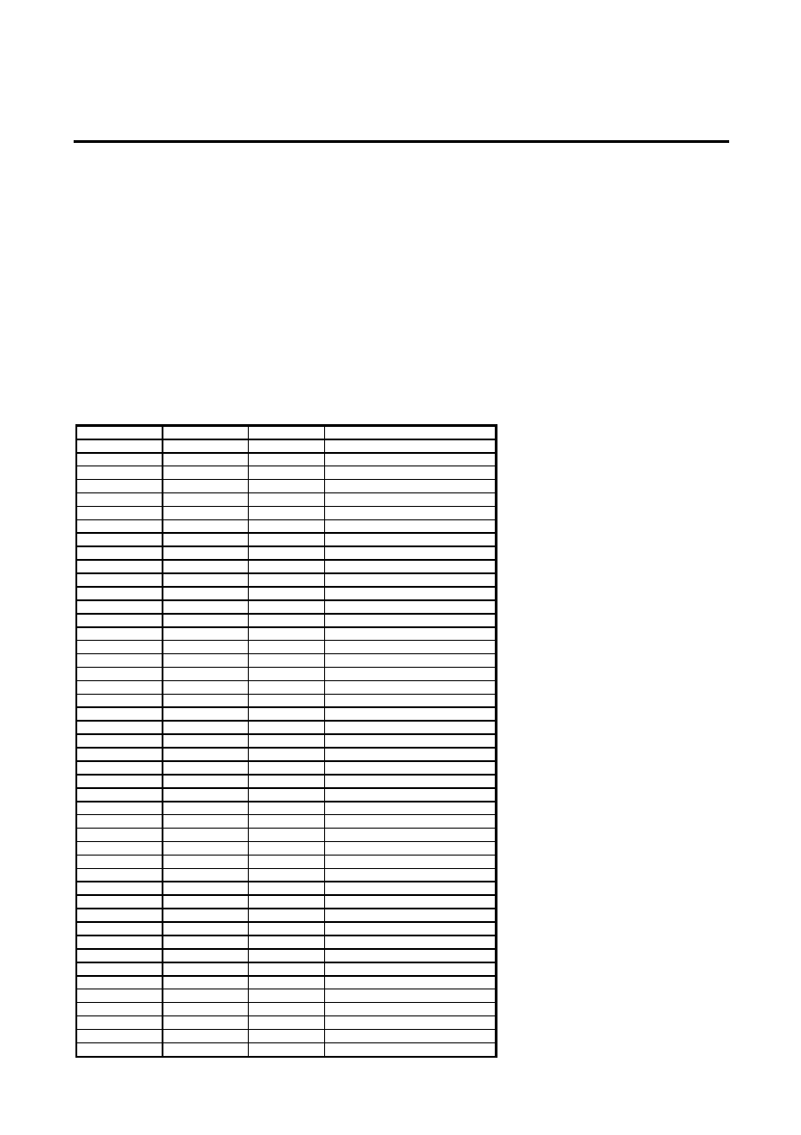
Pin Descriptions
Pin No
I/O
Symbol
Function
1
V
B
Connected as voltage doubler
2
V
A
Connected as voltage doubler
3
V
C
Connected as voltage doubler
4
GND
GND
5
O
H3
Signal to LCD (common)
6
O
H2
Signal to LCD (common)
7
O
c8
Signal to LCD (segment)
8
O
b8
Signal to LCD (segment)
9
O
a8
Signal to LCD (segment)
10
O
c7
Signal to LCD (segment)
11
O
b7
Signal to LCD (segment)
12
O
a7
Signal to LCD (segment)
13
O
c6
Signal to LCD (segment)
14
O
b6
Signal to LCD (segment)
15
O
a6
Signal to LCD (segment)
16
O
c5
Signal to LCD (segment)
17
O
b5
Signal to LCD (segment)
18
O
a5
Signal to LCD (segment)
19
O
c4
Signal to LCD (segment)
20
O
b4
Signal to LCD (segment)
21
O
a4
Signal to LCD (segment)
22
O
c3
Signal to LCD (segment)
23
O
b3
Signal to LCD (segment)
24
O
a3
Signal to LCD (segment)
25
O
c2
Signal to LCD (segment)
26
O
b2
Signal to LCD (segment)
27
O
a2
Signal to LCD (segment)
28
O
c1
Signal to LCD (segment)
29
O
b1
Signal to LCD (segment)
30
O
a1
Signal to LCD (segment)
31
O
H1
Signal to LCD (common)
32
V
DD
Positive power supply
33
I
APO
Auto power¡off option pad
34
I
VSO
Voltage limited option pad
35
I
K4
Key I/P signal
36
I
K6
Key I/P signal
37
I
K5
Key I/P signal
38
O
P1
Strobe signal to key
39
O
P2
Strobe signal to key
40
O
A5
Strobe signal to key
41
O
A4
Strobe signal to key
42
O
A3
Strobe signal to key
43
O
A2
Strobe signal to key
44
I
K2
Key I/P signal
45
I
K3
Key I/P signal
46
CG
Oscillator
O/P
Page 1 of 4
MIK9278F
8 Digit Calculator IC
February 2002
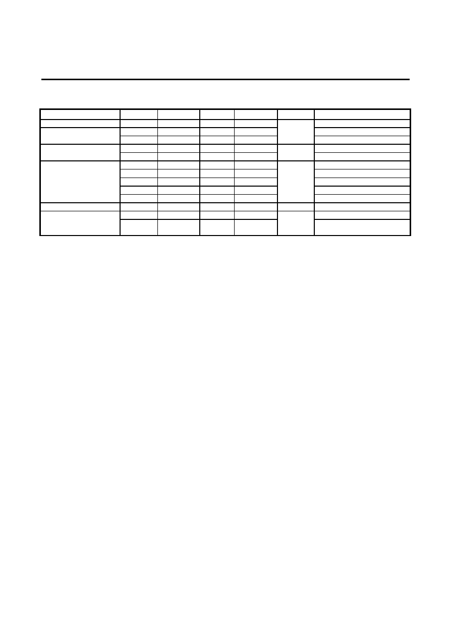
Electrical Characteristics
(V
DD
= 1.5 V, T
A
= 25
0
C, Unless otherwise specified)
Items Symbol
Min
Typ
Max
Units Conditions
Supply Voltage
V
CC
1.1 1.8
V
IL
¡ ¡ 0.4
Note
1
Input Voltage
V
IH
V
CC
-0.4 ¡
¡
V
Note 1
I
IH
0.3 1.0 3
V
IN
= V
CC
, Note 1
Input Current
I
IL
¡ ¡ 1
╡A
V
IN
= 0 V, Note 1
V
OH
V
CC
-0.15
¡
¡
No load, Note2
V
OL
¡ ¡ 0.15
I
OUT
= 15
╡A
, Note 2
V
OA
2.8 3.0
Note
3
V
OB
1.3 1.5 1.7
Note
3
Output Voltage
V
OC
¡ 0 0.2
V
Note 3
Display Frequency
F
d
55 _¡ ¡ Hz
V
CC
= 1.3 V Whiledisplay is on
I
OFF
¡
¡
0.1
Display is off, Note 4
Dissipation Current
I
DIS
¡ 3.5
5.0
╡A
V
CC
= 1.3 V Note 5
While
,
display is on
Note 1: Applies to terminals K2 - K6.
Note 2: Applies to terminals P1, P2 and A2 ¡ A5.
Note 3: Applies to terminals Hi(i=1-3), a
i
, b
i
and c
i
(i=1-8).
Note 4: Measured by the following test circuit after power supply automatically turns off.
Note 5: Measured by the above test circuit while "0" is being displayed after auto¡clear and while no key is being depressed.
Page 2 of 4