
02068-DSH-001-B
June 2003
CX02068
3.3 Volt Laser Driver IC for 155/622 Mbps
Data Sheet
Information provided in this Product Data Sheet is subject to change without notice.
Mindspeed TechnologiesTM, Inc, Proprietary and Confidential

02068-DSH-001-B
Page 2 of 16
CX02068
3.3 Volt Laser Driver IC for 155/622 Mbps
Information provided in this Product Data Sheet is subject to change without notice.
Mindspeed TechnologiesTM, Proprietary and Confidential
T
ABLE
OF
C
ONTENTS
Features . . . . . . . . . . . . . . . . . . . . . . . . . . . . . . . . . . . . . . . . . . . . . . . . . . . . . . . . . . . . . . . . . . . . . . . . . . . . . 3
Applications . . . . . . . . . . . . . . . . . . . . . . . . . . . . . . . . . . . . . . . . . . . . . . . . . . . . . . . . . . . . . . . . . . . . . . . . . . 3
Description . . . . . . . . . . . . . . . . . . . . . . . . . . . . . . . . . . . . . . . . . . . . . . . . . . . . . . . . . . . . . . . . . . . . . . . . . . . 3
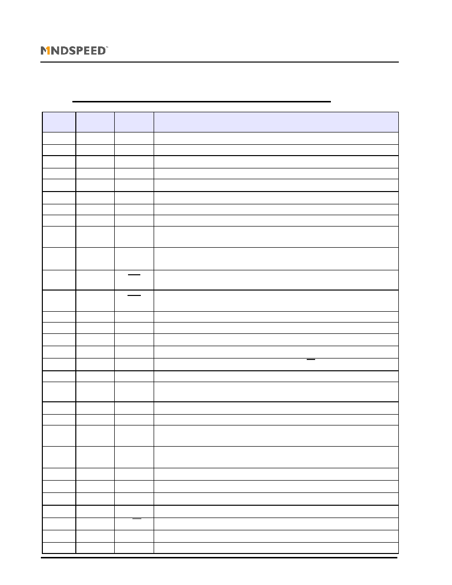
Table 1 Ordering Information . . . . . . . . . . . . . . . . . . . . . . . . . . . . . . . . . . . . . . . . . . . . . . . . . . . . . . . . . . . . . 3
Connections . . . . . . . . . . . . . . . . . . . . . . . . . . . . . . . . . . . . . . . . . . . . . . . . . . . . . . . . . . . . . . . . . . . . . . . . . . 3
Table 2 Pin Description - BCC+24 . . . . . . . . . . . . . . . . . . . . . . . . . . . . . . . . . . . . . . . . . . . . . . . . . . . . . . . . . 4
Table 3 Absolute Maximum Ratings. . . . . . . . . . . . . . . . . . . . . . . . . . . . . . . . . . . . . . . . . . . . . . . . . . . . . . . . 5
Table 4 Recommended Operating Conditions . . . . . . . . . . . . . . . . . . . . . . . . . . . . . . . . . . . . . . . . . . . . . . . . 5
Table 5 AC Characteristics. . . . . . . . . . . . . . . . . . . . . . . . . . . . . . . . . . . . . . . . . . . . . . . . . . . . . . . . . . . . . . . 6
Table 6 DC Characteristics. . . . . . . . . . . . . . . . . . . . . . . . . . . . . . . . . . . . . . . . . . . . . . . . . . . . . . . . . . . . . . . 7
Functional Diagram . . . . . . . . . . . . . . . . . . . . . . . . . . . . . . . . . . . . . . . . . . . . . . . . . . . . . . . . . . . . . . . . . . . . 8
Functional Description . . . . . . . . . . . . . . . . . . . . . . . . . . . . . . . . . . . . . . . . . . . . . . . . . . . . . . . . . . . . . . . . . . 8
Overview . . . . . . . . . . . . . . . . . . . . . . . . . . . . . . . . . . . . . . . . . . . . . . . . . . . . . . . . . . . . . . . . . . . . . . . . . . 8
Modulator. . . . . . . . . . . . . . . . . . . . . . . . . . . . . . . . . . . . . . . . . . . . . . . . . . . . . . . . . . . . . . . . . . . . . . . . . . 8
Typical modulation current vs RMOD
SET
(3.3 V) . . . . . . . . . . . . . . . . . . . . . . . . . . . . . . . . . . . . . . . . . . . . 8
Mean Power Control . . . . . . . . . . . . . . . . . . . . . . . . . . . . . . . . . . . . . . . . . . . . . . . . . . . . . . . . . . . . . . . . . 9
Typical
bias
current vs RBIAS
SET
(3.3 V) . . . . . . . . . . . . . . . . . . . . . . . . . . . . . . . . . . . . . . . . . . . . . . . . . 9
Typical limiting current vs R
OCA
(25
∞
C) . . . . . . . . . . . . . . . . . . . . . . . . . . . . . . . . . . . . . . . . . . . . . . . . . . 9
Temperature coefficient of Ioca at different ROCA settingst . . . . . . . . . . . . . . . . . . . . . . . . . . . . . . . . . . . 9
Enable Control. . . . . . . . . . . . . . . . . . . . . . . . . . . . . . . . . . . . . . . . . . . . . . . . . . . . . . . . . . . . . . . . . . . . . 10
Current Monitors . . . . . . . . . . . . . . . . . . . . . . . . . . . . . . . . . . . . . . . . . . . . . . . . . . . . . . . . . . . . . . . . . . . 10
Slow-Start . . . . . . . . . . . . . . . . . . . . . . . . . . . . . . . . . . . . . . . . . . . . . . . . . . . . . . . . . . . . . . . . . . . . . . . . 10
Temperature Compensation . . . . . . . . . . . . . . . . . . . . . . . . . . . . . . . . . . . . . . . . . . . . . . . . . . . . . . . . . . 10
Typical Eye Diagram . . . . . . . . . . . . . . . . . . . . . . . . . . . . . . . . . . . . . . . . . . . . . . . . . . . . . . . . . . . . . . . . 10
Temperature Compensation Graphs . . . . . . . . . . . . . . . . . . . . . . . . . . . . . . . . . . . . . . . . . . . . . . . . . . . . 11
Bare Die Information. . . . . . . . . . . . . . . . . . . . . . . . . . . . . . . . . . . . . . . . . . . . . . . . . . . . . . . . . . . . . . . . . . . 12
Table 7 Pad Centers. . . . . . . . . . . . . . . . . . . . . . . . . . . . . . . . . . . . . . . . . . . . . . . . . . . . . . . . . . . . . . . . . . . 12
TQFP32 Package Information . . . . . . . . . . . . . . . . . . . . . . . . . . . . . . . . . . . . . . . . . . . . . . . . . . . . . . . . . . . 13
Table 8 Package Dimensions. . . . . . . . . . . . . . . . . . . . . . . . . . . . . . . . . . . . . . . . . . . . . . . . . . . . . . . . . . . . 13
BCC+24L Package Information . . . . . . . . . . . . . . . . . . . . . . . . . . . . . . . . . . . . . . . . . . . . . . . . . . . . . . . . . . 14
SMT Mounting Guides . . . . . . . . . . . . . . . . . . . . . . . . . . . . . . . . . . . . . . . . . . . . . . . . . . . . . . . . . . . . . . . . . 14
Disclaimer. . . . . . . . . . . . . . . . . . . . . . . . . . . . . . . . . . . . . . . . . . . . . . . . . . . . . . . . . . . . . . . . . . . . . . . . . . . 15
Contact Information . . . . . . . . . . . . . . . . . . . . . . . . . . . . . . . . . . . . . . . . . . . . . . . . . . . . . . . . . . . . . . . . . . . 16

02068-DSH-001-B
Page 3 of 16
CX02068
3.3 Volt Laser Driver IC for 155/622 Mbps
Information provided in this Product Data Sheet is subject to change without notice.
Mindspeed TechnologiesTM, Proprietary and Confidential
F
EATURES
Rise and fall times <180 ps
Operates with +3.3 volt supply
DC or AC-coupled modulation drive.
Independently programmable laser bias
(to 100 mA) and modulation currents (to 85 mA).
Automatic laser power control, with
programmable temperature compensation and
`Slow-Start'.
Bias and modulation current monitors
Failure monitor
Available in BCC+24 , TQFP32 and DIE packages
A
PPLICATIONS
OC-3/STM1, SONET/SDH
OC-12/STM4, SONET/SDH
ATM
FTTH
D
ESCRIPTION
The CX02068 is a highly integrated, programmable laser
driver intended for Telecom applications up to 622 Mbps.
Using differential PECL data, the CX02068 supplies the
bias and modulation current for driving an edge-emitting
laser. The modulation output can be DC-coupled to the
laser diode, giving a significant power saving over AC-
coupled operation.
The CX02068 includes automatic power control (APC) to
maintain a constant average laser output power over
temperature and life. In addition, the modulation current
is temperature compensated to minimize variation in
extinction ratio over temperature.
Output flags indicate laser end of life as well as failure of
the APC circuitry to maintain average output power.
T
ABLE
1
O
RDERING
I
NFORMATION
C
ONNECTIONS
Note : For information on Die pad connections please see Fig. 13 on page12.
BCC+24L
TOP VIEW
TQFP32
TOP VIEW
Part Number
Pin Package
CX02068B24
BCC+24L
CX02068TQ32
TQFP32
CX02068DIEWP
Waffle pack
CX02068WAFER
Expanded whole 8" wafer on a 10"
grip ring
CX02068EVM
Evaluation board with a CX02068B24
2
3
4
5
6
7
8
9
10
11
12
13
14
15
16
17
18
19
24
23
22
21
20
1
ENA
DIS
FAIL
OCA
GND
BIAS
OU
T+
OU
T
-
PD
GND
GN
D
V
CC
GN
D
A
CMPC
TCSLOPE
TCSTART
MODSET
OCASET
D
IN
D
IN
V
CC
4mm
BIASMON
4mm
MODMON
V
CC
2068
1
2
7
6
5
4
3
8
24
23
18
19
20
21
22
17
12
9
10
11
15
14
13
16
29
32
31
30
26
27
28
25
N/C
N/C
N/C
ENA
DI
S
FA
I
L
OCA
GND
PD
OUT-
OUT+
BIAS
V CC
D IN
D IN
V CC
V CC
BI
A
S
MON
MOD
MON
V CC
V CC
V CC
GND
A
GND
A
V CC
C
MPC
NC
TC
SLO
P
E
GND
MOD
SE
T
OCA
SE
T
V
CC
5mm
5mm
Fig. 1
Fig. 2
02068-DSH-001-B
Page 4 of 16
CX02068
3.3 Volt Laser Driver IC for 155/622 Mbps
Information provided in this Product Data Sheet is subject to change without notice.
Mindspeed TechnologiesTM, Proprietary and Confidential
T
ABLE
2
P
IN
D
ESCRIPTIONS
Pin No
BCC+24
Pin No
TQFP32
Name
Function
-
18
V
CC
Power supply. All pins should be connected
-
22
GNDA
Ground to output stage.(inductor to ground to optimize output stage performance)
-
32
V
CC
Power supply. All pins should be connected
-
5, 6, 8, 27
NC
Not connected
-
7
V
CC
Power supply. All pins should be connected
-
25
V
CC
Power supply. All pins should be connected
1
9
ENA
Bias and modulation output enable (TTL/CMOS). HIGH for normal operation
2
10
DIS
Bias and modulation output disable (TTL/CMOS). LOW for normal operation
3
11
BIAS
MON
Bias monitor. Connect a resistor between this pin and V
CC
to monitor. Connect to V
CC
if
not in use.
4
12
MOD
MON
Modulation monitor. Connect a resistor between this pin and V
CC
to monitor. Connect to
V
CC
if not in use.
5
13
FAIL
Mean power control failure indicator (TTL/CMOS). Goes low when control loop is no
longer able to maintain constant current at PD
6
14
OCA
Over-Current Alarm (TTL/CMOS). Goes low when I
BIAS
exceeds the preset bias current
limit
7
-
GND
Ground. All pins should be connected
8
17
BIAS
Laser bias current output
9
1
V
CC
Power supply. All pins should be connected
10
19
OUT+
Positive modulation current output. Sinks current when D
IN
is HIGH.
11
20
OUT-
Negative modulation current output. Sinks current when D
IN
is HIGH.
12
23
GNDA
Ground to output stage.(inductor to ground to optimize output stage performance)
13
24
PD
Monitor photodiode input. This input is connected to the monitor photodiode anode for
automatic power control.
14
26
C
MPC
Mean power control dominant pole capacitor
15
15
GND
Ground. All pins should be connected
16
28
TC
SLOPE
Connecting a resistor between this pin and ground sets the temperature coefficient of
I
MODSET
(using the internal IC temperature).
17
-
TC
START
Secondary temperature coefficient of I
MOD
. A resistor on this pin to ground sets the
threshold temperature at which the temperature compensation starts.
18
30
MOD
SET
Modulation current set. Connect a resistor between this pin and ground
19
31
OCA
SET
Over current alarm set. Connect a resistor between this pin and ground
20
4
V
CC
Power supply. All pins should be connected
21
2
D
IN
Positive Data Input (PECL). Self biased.
22
3
D
IN
Negative Data Input (PECL). Self biased
23
16
V
CC
Power supply. All pins should be connected
24
29
GND
Ground. All pins should be connected

02068-DSH-001-B
Page 5 of 16
CX02068
3.3 Volt Laser Driver IC for 155/622 Mbps
Information provided in this Product Data Sheet is subject to change without notice.
Mindspeed TechnologiesTM, Proprietary and Confidential
T
ABLE
3
A
BSOLUTE
M
AXIMUM
R
ATINGS
These are the absolute maximum ratings at or beyond which the IC can be expected to fail or be damaged. Functional
operation at these levels is not implied.
T
ABLE
4
R
ECOMMENDED
O
PERATING
C
ONDITIONS
Parameter
Rating
Units
Power supply (V
CC
-GND)
-0.5 to +6.0
V
Operating ambient
-40 to +85
∞C
Storage temperature
-65 to +150
∞C
Maximum bias current
120
mA
Maximum laser modulation current (through OUT+/OUT2+, OUT-/OUT2-)
100
mA
Perimeter
Rating
Units
Power supply (V
CC
-GND)
3.3 ± 10%
V
Junction temperature (die)
-40 to +120
∞C
Operating ambient
-40 to +85
∞C