
02060-DSH-001-C
Page 2 of 18
M02060
3.3 Volt Laser Driver for Applications to 3 Gbps
Advance Info
rmatio
n
Information provided in this Data Sheet is Advance and is subject to change without notice.
Mindspeed TechnologiesTM , Proprietary and Confidential
T
ABLE
OF
C
ONTENTS
Features ...........................................................................................................................................................3
Applications ......................................................................................................................................................3
Description ........................................................................................................................................................3
Table 1 Ordering Information ............................................................................................................................3
Connections ......................................................................................................................................................3
Table 2 Pin Descriptions - MLF24 ....................................................................................................................4
Table 3 Absolute Maximum Ratings ................................................................................................................5
Table 4 Recommended Operating Conditions .................................................................................................5
Table 5 AC Characteristics ...............................................................................................................................6
Table 6 DC Characteristics ...............................................................................................................................7
Functional Diagram ..........................................................................................................................................8
Functional Description ......................................................................................................................................8
Overview ...........................................................................................................................................................8
Modulator ..........................................................................................................................................................8
Mean Power Control .........................................................................................................................................9
Table 7 MPC Loop Bandwidth ..........................................................................................................................9
Safety Logic ......................................................................................................................................................10
Data Input Latch ...............................................................................................................................................11
Enable Control ..................................................................................................................................................11
Typical Eye Diagram ........................................................................................................................................12
Temperature Compensation .............................................................................................................................13
Temperature Compensation (graph) ................................................................................................................13
Modulation Current Multiplier ............................................................................................................................13
Package Information .........................................................................................................................................14
Additional Package Information ........................................................................................................................15
Table 9 Features ..............................................................................................................................................15
Bare Die Information .........................................................................................................................................16
Table 10 Pad Centers .......................................................................................................................................16
Disclaimer .........................................................................................................................................................16
Contact Information ...........................................................................................................................................17
02060-DSH-001-C
Page 3 of 18
M02060
3.3 Volt Laser Driver for Applications to 3 Gbps
Advance Info
rmatio
n
Information provided in this Data Sheet is Advance and is subject to change without notice.
Mindspeed TechnologiesTM, Proprietary and Confidential
F
EATURES
!
High speed operation; suitable for applications to 3 Gbps
!
Typical rise/fall times of 90 ps
!
DC or AC-coupled modulation drive
!
Differential data and clock inputs to minimize pattern
dependent jitter
!
Independently Programmable Laser Bias and Modulation
currents
!
Bias current to 100 mA and modulation current to 85 mA
at V
CC
= 3.3 V
!
Automatic Laser Power Control, with programmable
temperature compensation and `Slow-Start'
!
Maximum laser current limit configuration using the pin
V
CC
LD
!
Operates with +3.3 Volt supply
!
The M02060 is available in die form, or packaged MLF24
!
Comprehensive built-in eyesafety
A
PPLICATIONS
!
Short reach SONET/SDH
!
Metro SONET/SDH
!
Add/Drop Multiplexers
!
Digital Cross Connects
!
SFP compliant
D
ESCRIPTION
The M02060 is a highly integrated, programmable laser driver
intended for SONET/SDH applications with FEC to 3 Gbps.
Using differential PECL data and clock inputs, the M02060
supplies the bias and modulation current required to drive an
edge-emitting laser. The modulation output can be DC-coupled
to the laser diode, giving a significant power saving over AC-
coupled operation.
The M02060 includes automatic power control to maintain a
constant average laser output power over temperature and life.
In addition, the modulation current can be temperature
compensated to minimize variation in extinction ratio over
temperature.
Output flags indicate laser end of life as well as failure in the
device which may result in an eyesafety hazard.
T
ABLE
1
O
RDERING
I
NFORMATION
C
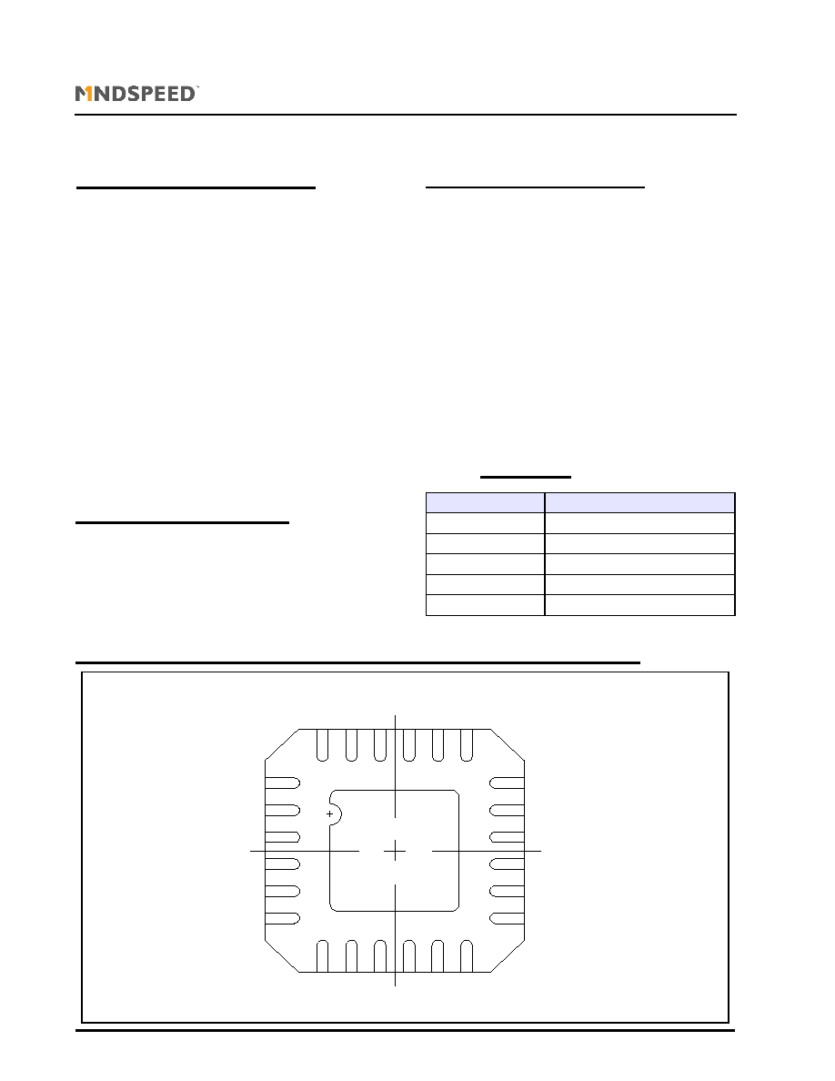
ONNECTIONS
Part Number
Pin Package
M02060DIEWP
Waffle pack
M02060WAFER
Expanded wafer on a grip ring
M02060-21P
24 pin MLF, 20 ps max DCD
M02060-51P
24 pin MLF, 50 ps max DCD
M02060evm-el
Electrical evaluation board
Fig. 1
CEN
DIS
GND
V
CC
LD
SV
CC
OU
T
+
V
CC
D
IN
__
_
D
IN
__
_
CL
K
____
OCA
V
CC
BI
A
S
OU
T
-
GN
D
A
PD
TC
SLOPE
TC
START
MOD
SET
OCA
SET
GN
D
CL
K
C
MPC
______
FAULT
1
6
7
12
13
18
19
24
02060-DSH-001-C
Page 4 of 18
M02060
3.3 Volt Laser Driver for Applications to 3 Gbps
Advance Info
rmatio
n
Information provided in this Data Sheet is Advance and is subject to change without notice.
Mindspeed TechnologiesTM, Proprietary and Confidential
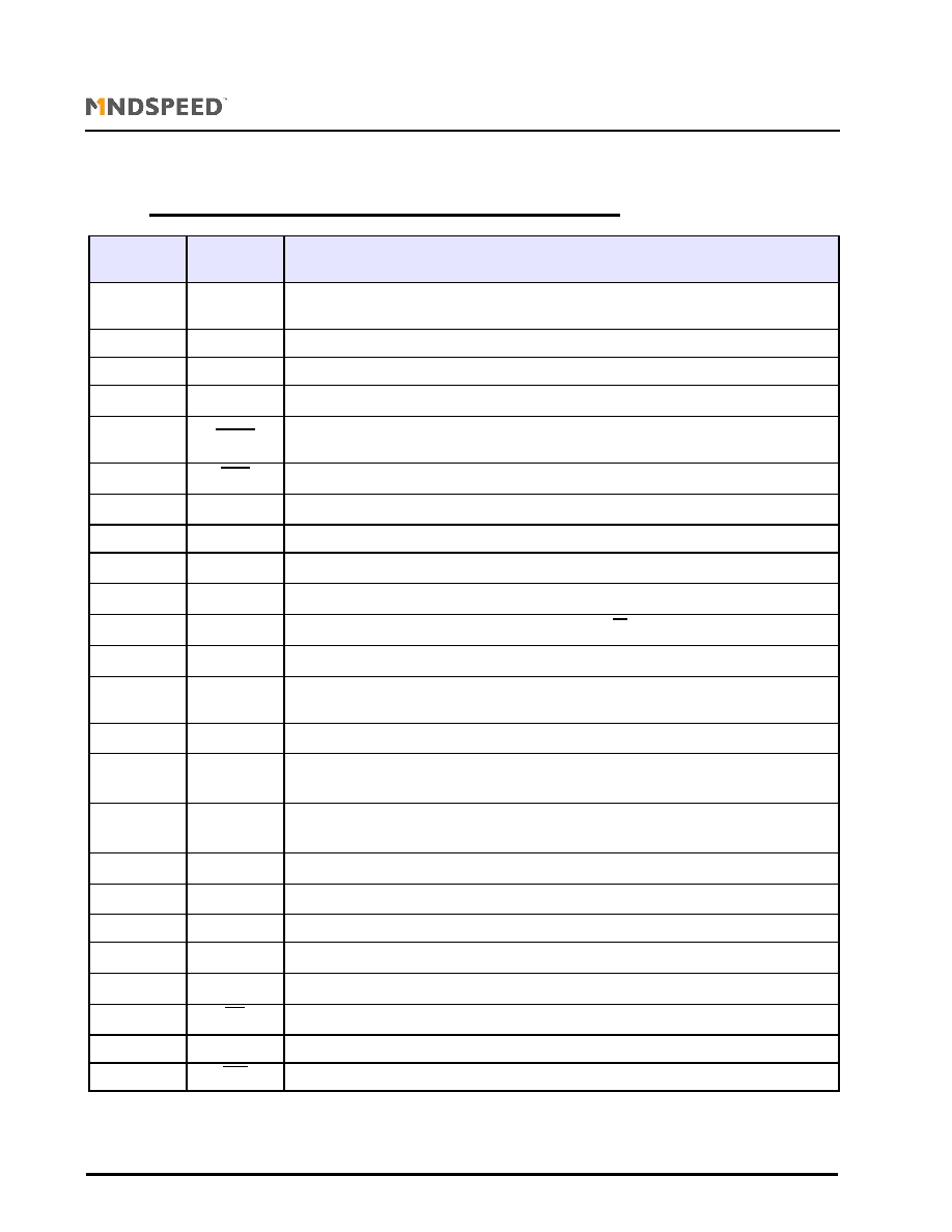
T
ABLE
2
P
IN
D
ESCRIPTIONS
- MLF24
Note: Center pad (pad 25) is not connected but should be soldered to a ground pad for thermal dissipation
Pin Number
MLF24
Name
Function
1
CEN
Clock enable input (TTL/CMOS). Set HIGH or not connected to use CLK inputs, LOW when not
using CLK inputs
2
DIS
Bias and modulation output disable (TTL/CMOS). LOW for normal operation
3
GND
Ground
4
V
CC
LD
Current limited positive supply, connect to Vcc through sense resistor RLD
5
FAULT
Mean power control failure indicator (TTL/CMOS). Goes LOW when control loop is no longer
able to maintain a safe current in the laser. SVcc is disabled when FAULT(bar) is low.
6
OCA
Over-current alarm (TTL/CMOS). Goes LOW when I
BIAS
exceeds the preset bias current limit
7
V
CC
Power supply
8
BIAS
Laser bias current output
9
SV
CC
Positive supply to laser anode and photodiode cathode
10
OUT+
Positive modulation current output. Sinks current when D
IN
is HIGH
11
OUT-
Negative modulation current output. Sinks current when D
IN
is HIGH
12
GND
A
Ground for output stage. (connect to ground through an inductor)
13
PD
Monitor photo diode input. This input is connected to the monitor photodiode anode for
automatic power control
14
C
MPC
Mean power control loop dominant pole capacitor (capacitor must be tied to V
cc
, not GND).
15
TC
SLOPE
Connecting a resistor between this pin and ground sets the temperature coefficient of I
MODSET
(using the internal IC temperature). To disable TCSLOPE, leave open.
16
TC
START
Secondary temperature coefficient of I
MOD
. A resistor on this pin to ground sets the temperature
at which the temperature compensation starts. To disable TCSTART, connect to ground.
17
MOD
SET
Modulation current set. Connect a resistor between this pin and ground to set
18
OCA
SET
Over current alarm set. Connect a resistor between this pin and ground to set
19
GND
Ground
20
V
CC
Power supply
21
D
IN
Positive data input (PECL). Self biased
22
D
IN
Negative data input (PECL). Self biased
23
CLK
Positive clock input (PECL). Self biased. Connect to Vcc if not used.
24
CLK
Negative clock input (PECL). Self biased. Can be disconnected if not used
02060-DSH-001-C
Page 5 of 18
M02060
3.3 Volt Laser Driver for Applications to 3 Gbps
Advance Info
rmatio
n
Information provided in this Data Sheet is Advance and is subject to change without notice.
Mindspeed TechnologiesTM, Proprietary and Confidential
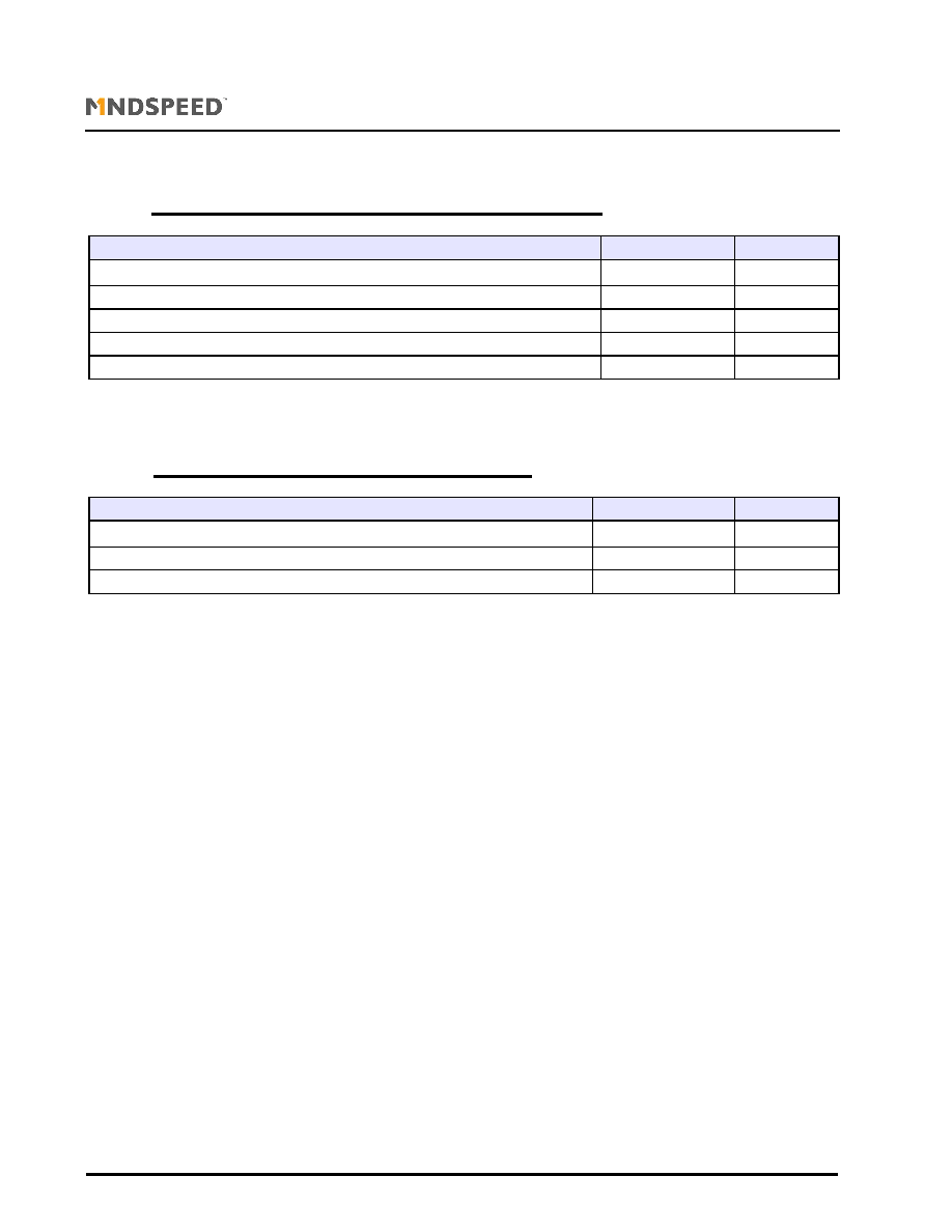
T
ABLE
3
A
BSOLUTE
M
AXIMUM
R
ATINGS
These are the absolute maximum ratings at or beyond which the IC can be expected to fail or be damaged. Reliable
operation at these extremes for any length of time is not implied.
T
ABLE
4
R
ECOMMENDED
O
PERATING
C
ONDITIONS
Parameter
Rating
Units
Power supply (V
CC
-GND)
-0.5 to +6.0
V
Operating ambient
-40 to +85
∞C
Storage temperature
-65 to +150
∞C
Maximum laser bias current
120
mA
Maximum laser modulation current (through OUT+/OUT2+, OUT-/OUT2-)
100
mA
Parameter
Rating
Units
Power supply (V
CC
-GND)
3.3 ± 10%
V
Junction temperature (die)
-40 to + 120
∞C
Operating ambient
-40 to + 85
∞C