
02042-DSH-001-B 2/03
February 2003
Preliminary Info
rmation
MC2042-4
LED/Laser Driver for FDDI, Fast Ethernet, Fibre Channel, OC3/STM-1,
IEEE1394
Data Sheet
Features
Description
Applications
Pin Descriptions
Measurement Tables
Functional Description
Features
Description
Applications
Pin Descriptions
Measurement Tables
Functional Description
Information provided in this Data Sheet is PRELIMINARY and is subject to change without
notice. MindspeedTM Technologies, Inc, Proprietary and Confidential

02042-DSH-001-B 2/03
Page 2 of 13
MC2042-4
LED/Laser Driver for FDDI, Fast Ethernet, Fibre Channel, OC3/STM-1, IEEE1394
Preliminary In
formation
Information provided in this Data Sheet is PRELIMINARY and is subject to change without notice.
MindspeedTM Technologies, Proprietary and Confidential
T
ABLE
OF
C
ONTENTS
Features ...........................................................................................................................................................3
Applications ......................................................................................................................................................3
Connections ......................................................................................................................................................3
General Description ..........................................................................................................................................3
Table 1 Ordering Information ............................................................................................................................3
Top Level Diagram ...........................................................................................................................................3
Table 2 Pin Descriptions ...................................................................................................................................4
Table 3 Absolute Maximum Ratings .................................................................................................................5
Table 4 DC Electrical Characteristics ...............................................................................................................5
Table 5 AC Electrical Characteristics ...............................................................................................................5
Typical Applications Circuit ...............................................................................................................................6
Functional Description ......................................................................................................................................6
Current Switch ..................................................................................................................................................6
LED Drive and Temperature Compensation ....................................................................................................6
Transmit Enable/Disable ..................................................................................................................................7
Pre-emphasis or `Peaking' ................................................................................................................................7
LED clamping, Laser driving .............................................................................................................................7
LED drive Pulse Width Adjust (PWA) ...............................................................................................................8
Temperature Compensation..............................................................................................................................8
Eye Diagram......................................................................................................................................................8
Evaluation Board ...............................................................................................................................................9
Bare Die ..........................................................................................................................................................10
Table 6 Bare Die Pad Coordinates ...................................................................................................................10
TSSOP20 Package Information .......................................................................................................................11
QSOP16 Package Information .........................................................................................................................12
Table 7 TSSOP20 Dimensions .........................................................................................................................12
Table 8 QSOP16 Dimensions ..........................................................................................................................12
Disclaimer .........................................................................................................................................................13
Contact Information ...........................................................................................................................................14
02042-DSH-001-B 2/03
Page 3 of 14
MC2042-4
LED/Laser Driver for FDDI, Fast Ethernet, Fibre Channel, OC3/STM-1, IEEE1394
Preliminary In
formation
Information provided in this Data Sheet is PRELIMINARY and is subject to change without notice.
MindspeedTM Technologies, Proprietary and Confidential
F
EATURES
!
Data rates to >300 Mbps, depending on LED
!
Single chip solution, available as die or in TSSOP20
or QSOP16 fabricated in deep sub-micron CMOS for
lowest cost & power consumption and long term
reliability
!
Programmable output current from 5 mA to 100 mA
!
RC programmable pre-emphasis or `peaking' circuit
giving drive current rise and fall times <500 ps
!
Resistor programmable compensation for
temperature dependence of LED output power
!
PECL input with optional Pulse Width Adjust
!
Single-ended CMOS input compatible at low speeds
!
V
REF
voltage generator and output pin
!
Supports most LED types (e.g. 660 to 1300 nm)
!
Single +5 V to +3.3 V operation
A
PPLICATIONS
!
FDDI, fiber Channel
!
Fast Ethernet, IEEE1394
!
OC3/STM1
C
ONNECTIONS
G
ENERAL
D
ESCRIPTION
The MC2042-4 is a CMOS IC designed for high-speed
LED drive in low-cost optical fiber based transmission
systems. Depending on the LED used, data rates to
>300Mbps can be achieved.
The LED drive current is set by a resistor. To improve LED
`on' time, a pre-emphasis circuit is included, which may be
set via a simple RC network.
To minimize the effects of temperature on LED output
power, LED drive temperature compensation can be set
by resistor over a 500 - 10,000 ppm/�C range.
Differential positive-ECL (PECL) data on the input pins
can be shaped, if desired, by the differential voltage on
the Pulse Width Adjust (PWA) pins. This adjustment is
continuous over a �500 ps range. In addition, the V
REF
output pin allows single-ended input to the MC2042 and
provides compatibility with industry-standard FO
modules.
T
ABLE
1
O
RDERING
I
NFORMATION
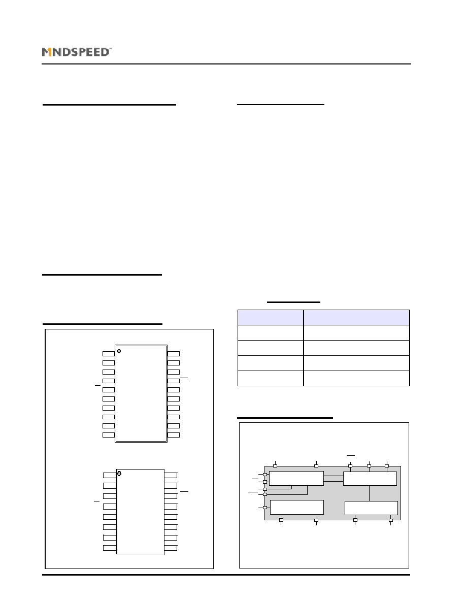
T
OP
L
EVEL
D
IAGRAM
6.5 x 4.4mm TSSOP Package
4.3 x 3.9mm QSOP Package
1
2
3
4
5
6
7
8
9
10
20
19
18
17
16
15
14
13
12
11
MC2042-4
Datecode
PWA-
NC
D
IN
D
IN
V
REF
RE
SET2
RT
SET
V
DD1
PWA-
NC
GND
V
DD2
GND
I
OUT
I
OUT
I
OUT
PEAK
V
DD2
NC
NC
TSSOP20
1
2
3
4
5
6
7
8
16
15
14
13
12
11
10
9
MC2042-4
Datecode
GND
V
DD2
GND
I
OUT
I
OUT
I
OUT
PEAK
V
DD2
QSOP16
PWA-
V
DD1
PWA+
D
IN
D
IN
V
REF
RT
SET2
RT
SET
Fig.1
TOP VIEWS
Part
Pin-Package
MC2042-4DIEWP
Waffle pack
MC2042-4WAFER
Expanded Whole Wafer on a ring
MC2042-4Q16
QSOP16
MC2042-4T20
TSSOP20
Fig. 2
Inp ut Data Pulse Shap ing
V
R EF
G enerator
GN D
G ND
R T
SET
RT
SET 2
PEAK
V
DD2
V
DD1
D
IN
PW A
I
O UT
PW A
D
IN
V
R E F
C urrent Switch and Peaking
Control
Program m able
Current Sink
I
O UT

02042-DSH-001-B 2/03
Page 4 of 14
MC2042-4
LED/Laser Driver for FDDI, Fast Ethernet, Fibre Channel, OC3/STM-1, IEEE1394
Preliminary In
formation
Information provided in this Data Sheet is PRELIMINARY and is subject to change without notice.
MindspeedTM Technologies, Proprietary and Confidential
T
ABLE
2
P
IN
D
ESCRIPTIONS
TSSOP20
Pin
QSOP16
Pin
Die
Pin
Name
Description
1
-
-
NC
Not connected, leave open
2
1
13
PWA
Inverse pulse width adjust input
3
2
14
PWA
Differential pulse width adjust input. Allows continuous adjustment of input data
pulse width
4
3
15
D
IN
Differential data input
5
4
16
D
IN
Inverse differential data input
6
5
1
V
REF
Reference output. Can be used with single-ended data input
7
6
2
RT
SET2
Temperature compensation adjustment pin. Allows temperature dependence of
LED light output to be reduced or removed
8
7
3
RT
SET
Sets nominal LED drive current
9
8
4
V
DD1
Power pin, connect to most positive supply
10
-
-
NC
Not connected
11
-
-
NC
Not connected
12
9
5
V
DD2
LED shorting pin, connect to most positive supply. Speeds LED switch off
13
10
6
V
DD2
LED shorting pin, connect to most positive supply. Speeds LED switch off
14
11
7
PEAK
Connection for pre-emphasis or peaking circuit
15
12
8
I
OUT
Driver output. Connect LED between this pin and V
DD
16
13
9
I
OUT
Driver output. Connect LED between this pin and V
DD
17
14
10
I
OUT
Logical inverse of pin 8. Connect resistor of approximately the same value as
LED (at the programmed drive current level) between this pin and V
DD
18
15
11
GND
Ground pin. Connect to the most negative supply
19
16
12
GND
Ground pin. Connect to the most negative supply
20
-
-
NC
Not connected, leave open

02042-DSH-001-B 2/03
Page 5 of 14
MC2042-4
LED/Laser Driver for FDDI, Fast Ethernet, Fibre Channel, OC3/STM-1, IEEE1394
Preliminary In
formation
Information provided in this Data Sheet is PRELIMINARY and is subject to change without notice.
MindspeedTM Technologies, Proprietary and Confidential
T
ABLE
3
A
BSOLUTE
M
AXIMUM
R
ATINGS
These are the absolute maximum ratings at or beyond which the IC can be expected to fail or be damaged. Reliable
operation at these extremes for any length of time is not implied.
T
ABLE
4
DC E
LECTRICAL
C
HARACTERISTICS
T
ABLE
5
AC E
LECTRICAL
C
HARACTERISTICS
Symbol
Parameter
Rating
Units
P
TOT
Total power dissipation (TSSOP20)
255
mW
V
CC
Power supply (V
CC
-GND)
7
V
T
J
Junction temperature
150
�C
T
A
Operating ambient
-40 to +85
�C
T
STG
Storage temperature
-65 to +50
�C
Symbol
Parameter
Min
Typ
Max
Units
V
CC
Supply Voltage
3.0
-
5.5
V
Din
Allowable voltage at data inputs
Gnd - 0.3
-
V
CC
+0.3
V
REF
Voltage reference
V
CC
-1.6
V
CC
-1.4
V
CC
-1.03
I
LED'
ON
LED drive current
5
-
120
mA
I
LED'
OFF
LED off current
-
-
50
�A
I
COMP
LED drive current temperature compensation range
0.05
-
1
%/�C
V_LED_H
LED headroom voltage
-
-
V
DD
-2.0
V
Symbol
Parameter
Min
Typ
Max
Units
Vin(Diff)
Differential Input Voltage, 2*(DinH - DinL)
300mV
-
2*Vcc
V
Common Mode Input Voltage
V
CC
/2
-
(V
cc
-(V
in
[Diff])/4)
V
f
C
Maximum data rate
300
-
-
Mbps
T
PWA
Input data pulse width adjust range
-500
-
500
ps
LED t
r
LED drive rise time
-
0.7
1
ns
LED t
f
LED drive fall time
-
0.7
1
ns
I
PEAK
Peaking current (as % of LED drive current)
0
-
50
%
PEAK t
r
Peaking current rise time
-
-
1
ns
PEAK t
f
Peaking current fall time
-
-
1
ns
PEAK t
d
Peaking current decay time
-
C1x(R4+5)
-
S
I
DD
Supply current
-
I
LED
+10
I
LED
+20
mA