INTERNET
http://www.minicircuits.com
P.O. Box 350166, Brooklyn, New York 11235-0003 (718) 934-4500 Fax (718) 332-4661
Distribution Centers NORTH AMERICA 800-654-7949 ∑ 417-335-5935 ∑ Fax 417-335-5945 ∑ EUROPE 44-1252-832600 ∑ Fax 44-1252-837010
Mini-Circuits
Æ
Mini-Circuits ISO 9001 & ISO 14001 Certified
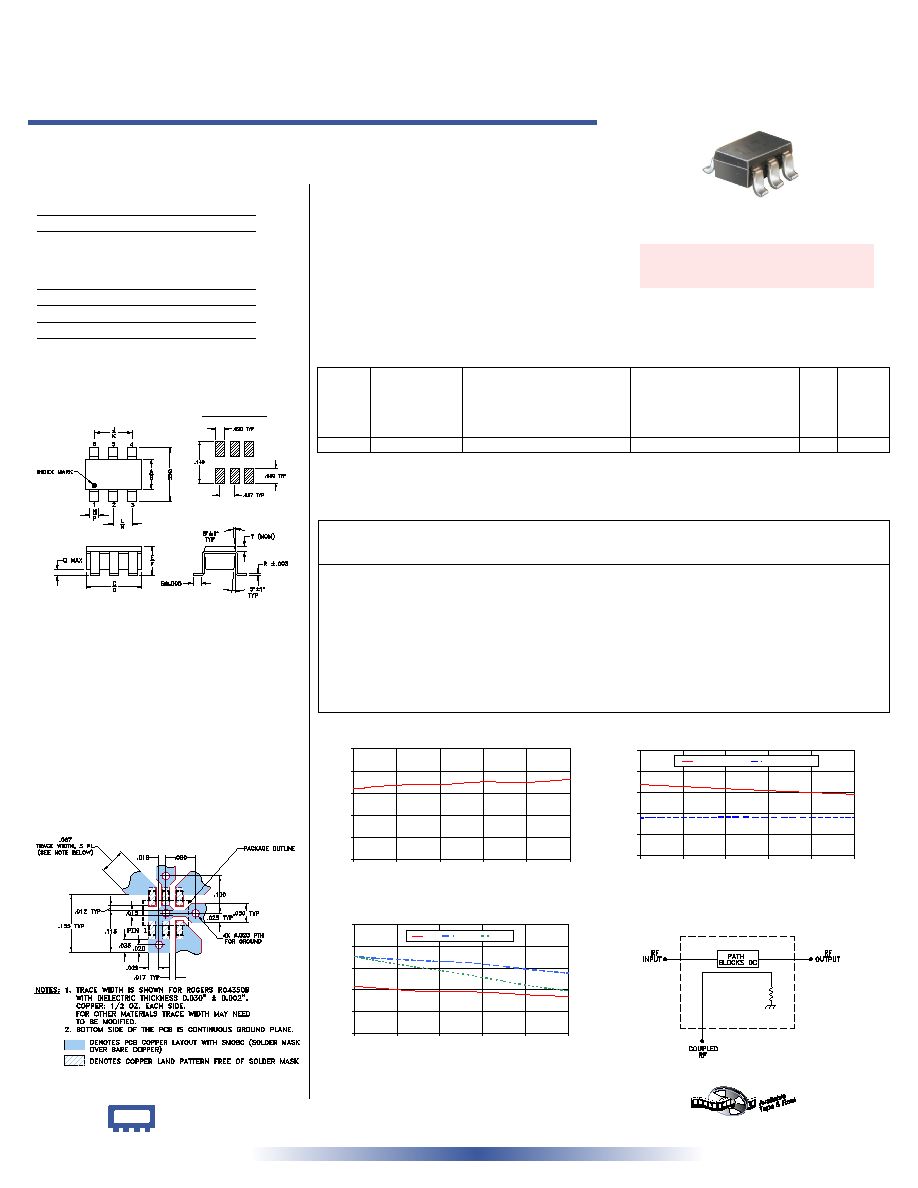
PCB Land Pattern
Suggested Layout,
Tolerance to be within
±.002
50 810 to 960 MHz
Directional Coupler
Surface Mount
CASE STYLE: CA531
PRICE: $ 0.99 ea. QTY (25)
Demo Board MCL P/N: TB-13
Suggested PCB Layout (PL-064)
Outline Dimensions ( )
inch
mm
Maximum Ratings
Pin Connections
INPUT
4
OUTPUT
6
COUPLED
3
GROUND
1,2,5
Outline Drawing
Directional Coupler Electrical Specifications
REV. C
M102713
D20C
JS/TD/CP
060721
A
B
C
D
E
F
G
H
J
.052
.067
.106
.122
.035
.064
.087
.118
.067
1.32
1.70
2.69
3.10
0.89
1.63
2.21
3.00
1.70
K
L
M
N
P
Q
R
S
T
wt
.083
.033
.042
.012
.020
.012
.007
.020
.012 grams
2.11
0.84
1.07
0.30
0.51
0.30
0.18
0.51
0.30 0.020
Typical Performance Data
+ RoHS compliant in accordance
with EU Directive (2002/95/EC)
The +Suffix identifies RoHS Compliance. See our web site
for RoHS Compliance methodologies and qualifications.
D20C+
D20C
Operating Temperature
-40∞C to 85∞C
Storage Temperature
-65∞C to 150∞C
Features
∑ low insertion loss, 0.3 dB typ.
∑ excellent VSWR, 1.1:1 typ.
∑ excellent repeatability
∑ miniature low profile SOT 6 package
Applications
∑ cellular
∑ PCS
D20C
MAINLINE LOSS
0.0
0.1
0.2
0.3
0.4
0.5
810
840
870
900
930
960
FREQUENCY (MHz)
MAINLINE
LOSS
(dB)
at RF level of -10 dBm
D20C
COUPLING & DIRECTIVITY
10
13
16
19
22
25
810
840
870
900
930
960
FREQUENCY (MHz)
C
O
U
P
L
I
N
G
&
D
I
R
E
C
T
I
V
I
T
Y
(
d
B
)
COUPLING
DIRECTIVITY
at RF level of -10 dBm
D20C
RETURN LOSS
25
27
29
31
33
35
810
840
870
900
930
960
FREQUENCY (MHz)
R
E
T
U
R
N
L
O
S
S
(
d
B
)
IN
OUT
CPL
at RF level of -10 dBm
electrical schematic
Frequency
(MHz)
Mainline Loss
(dB)
In-Out
Coupling
(dB)
In-Cpl
Directivity
(dB)
In
Return Loss
(dB)
Out
Cpl
ESD Rating
Human Body Model (HBM): Class 1A (250 v to <500 v) in accordance with ANSI/ESD STM 5.1 - 2001
Machine Model (MM): Class M1 (< 100 v) in accordance with ANSI/ESD STM 5.2 - 1999 (pass 50V)
810.00
0.32
20.15
15.42
29.31
32.09
32.06
815.00
0.32
20.10
15.43
29.27
32.02
31.93
825.00
0.33
20.00
15.44
29.17
31.91
31.69
855.00
0.34
19.71
15.49
28.87
31.70
31.05
875.00
0.34
19.51
15.51
28.80
31.59
30.69
895.00
0.35
19.33
15.50
28.80
31.44
30.26
915.00
0.35
19.15
15.48
28.68
31.15
29.79
935.00
0.35
18.97
15.48
28.51
30.84
29.34
955.00
0.36
18.80
15.49
28.41
30.60
29.00
960.00
0.36
18.76
15.50
28.37
30.54
28.92
1. Mainline loss includes therotertical power loss at coupled port.
2. 4W CW when operating with a 2.0:1 maximum VSWR on all ports.
FREQ.
RANGE
(MHz)
COUPLING
(dB)
MAINLINE LOSS
1
(dB)
DIRECTIVITY
(dB)
VSWR
(:1)
POWER
INPUT
2
Typ. Max.
Typ.
Min.
Typ.
Max.
810-960
19.4±1.4
0.3
0.5
15
7
1.1
1.0