Directional Coupler Electrical Specifications
Features
∑ VHF/UHF receivers/transmitters
∑ cellular
∑ very flat coupling
∑ very broadband, multi octave
∑ temperature stable, BLUE CELLTM base
∑ all welded construction
∑ leads attached for better solderibility
∑ micro-miniature coupler
∑ protected by U.S. Patent 6,140,887 & 6,784,521
Applications
FREQ.
RANGE
(MHz)
COUPLING
(dB)
f
L
-f
U
5-1000
12.2±0.5
±0.9
0.9
1.8
0.7 1.3
1.1 1.6
33
22
21
14
15
--
1.20
0.5
1.0
VSWR**
(:1)
Nom.
Max.
Flatness
POWER
INPUT, W
L
Max.
MU
Max.
MAINLINE LOSS*
(dB)
L
Typ. Max.
M
Typ. Max.
U
Typ. Max.
DIRECTIVITY
(dB)
L
Typ. Min.
M
Typ. Min.
U
Typ. Min.
Typ.
Typical Performance Data
BLUE CELLTM is protected by U.S. Patents.
Frequency
(MHz)
Insertion Loss
(dB)
In-Out
Coupling
(dB)
In-Cpl
Directivity
(dB)
Return Loss
(dB)
In
Cpl
Out
* Includes theoretical coupled power loss of 0.27 dB at 12 dB coupling.
** For coupled port VSWR above 500 MHz, 1.5:1 typ.
L = low range [f
L
to 10 f
L
] M = mid range [10 f
L
to f
U
/2] U = upper range [f
U
/2 to f
U
]
5.00
0.88
12.07
34.34
19.19
23.31
17.81
10.00
0.79
11.96
34.86
21.25
27.96
19.68
50.00
0.73
11.90
35.53
22.99
35.09
21.01
100.00
0.75
11.93
37.41
22.94
34.58
21.11
500.00
0.85
11.99
25.82
22.00
26.19
18.96
600.00
0.88
11.99
22.32
21.56
25.58
17.94
800.00
0.95
12.03
17.75
20.94
25.46
15.62
900.00
1.00
12.07
16.15
20.79
26.14
14.55
1000.00
1.06
12.13
14.74
20.48
26.70
13.43
DBTC-12-4L
COUPLING & DIRECTIVITY
0.0
5.0
10.0
15.0
20.0
25.0
30.0
35.0
40.0
0
200
400
600
800
1000
FREQUENCY (MHz)
C
O
UP
L
I
NG
&
DI
RE
C
T
I
V
I
T
Y
(
d
B
)
COUPLING
DIRECTIVITY
DBTC-12-4L
RETURN LOSS
0.0
5.0
10.0
15.0
20.0
25.0
30.0
35.0
40.0
0
200
400
600
800
1000
FREQUENCY (MHz)
RETURN L
O
SS (
d
B)
IN
OUT
CPL
at RF level of -10 dBm
DBTC-12-4L
INSERTION LOSS
0.0
0.2
0.4
0.6
0.8
1.0
1.2
0
200
400
600
800
1000
FREQUENCY (MHz)
I
N
SERTI
ON LOSS (
d
B)
at RF level of -10 dBm
No Leads
CASE STYLE:AT790-1
PRICE: $1.99 ea. QTY (25)
$1.69 ea. QTY (1000)
Leads
CASE STYLE:AT1030
PRICE: $2.14 ea. QTY (25)
$1.84 ea. QTY (1000)
DBTC-12-4
NEW!
DBTC-12-4L
Maximum Ratings
Pin Connections
INPUT
3
OUTPUT
4
COUPLED
1
GROUND
2
NOT USED*
5,6
Operating Temperature
-40∞C to 85∞C
Storage Temperature
-55∞C to 100∞C
*pins 5&6 must be isolated
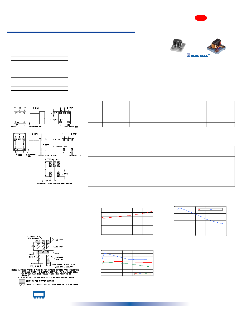
Outline Drawing
AT1030
A
B
C
D
E
F
G
H
J
K
L
wt.
.166 .150 .155 .050 .037 .025 .012 .060 .184 .030 .004 grams
4.22 3.81 3.94 1.27 0.94 0.64 0.30 1.52 4.67 0.76 0.10
.10
AT790-1 A
B
C
D
E
F
G
H
J
K
wt.
.150 .150 .150 .050 .030 .025 .028 .050 .160 .030
grams
3.81 3.81 3.81 1.27 0.76 0.64 0.71 1.27 4.06 0.76
.10
Outline Dimensions ( )
inch
mm
Demo Board MCL P/N: TB-278
Suggested PCB Layout (PL-150)
Reflow Solder Assembly
Silver-bearing solder (Sn/Pb/Ag 62/36/2%) is recommended;
however, tin-lead eutectic (Sn/Pb 63/37%) may be used.
For temperature profiles, see Application Note AN-40-004
AT790-1
AT1030
AT790-1 & AT1030
REV. F
M89619
DBTC-12-4
ED-8954/1
DBTC-12-4L ED-8954A
WZ/TD/CP
040225
50
5 to 1000 MHz
Directional Couplers
Surface Mount
INTERNET http://www.minicircuits.com
P.O. Box 350166, Brooklyn, New York 11235-0003 (718) 934-4500 Fax (718) 332-4661
Distribution Centers
NORTH AMERICA 800-654-7949 ∑ 417-335-5935 ∑ Fax 417-335-5945 ∑ EUROPE 44-1252-832600 ∑ Fax 44-1252-837010
Mini-Circuits
Æ
Mini-Circuits ISO 9001 & ISO 14001 Certified