INTERNET
http://www.minicircuits.com
P.O. Box 350166, Brooklyn, New York 11235-0003 (718) 934-4500 Fax (718) 332-4661
Distribution Centers NORTH AMERICA 800-654-7949 ∑ 417-335-5935 ∑ Fax 417-335-5945 ∑ EUROPE 44-1252-832600 ∑ Fax 44-1252-837010
Mini-Circuits
Æ
Mini-Circuits ISO 9001 & ISO 14001 Certified
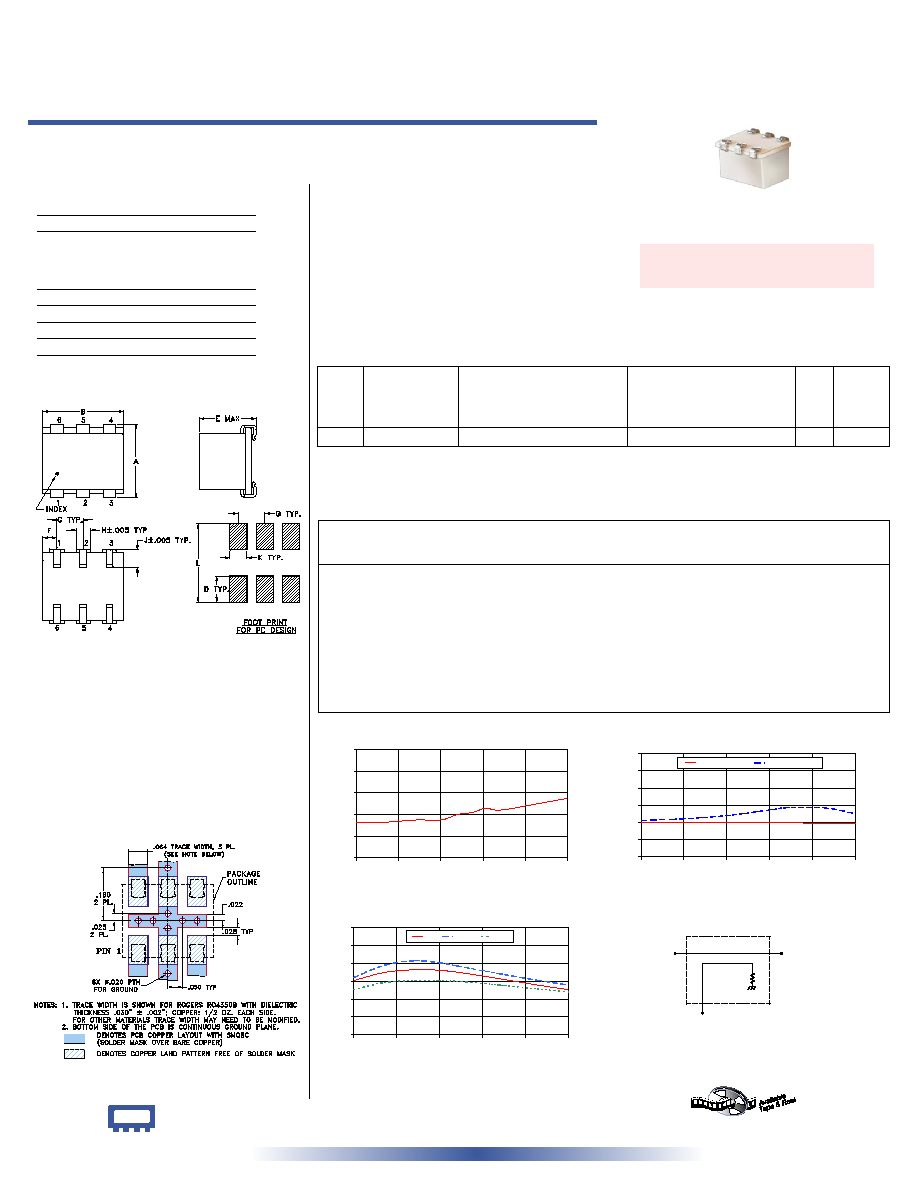
A
B
C
D
E
F
G
.280
.310
--
.100
.225
.055
.100
7.11
7.87
--
2.54
5.72
1.40
2.54
H
J
K
L
wt
.047
.065
.065
.300
grams
1.19
1.65
1.65
7.62
0.45
50 50 to 750 MHz
Directional Coupler
Surface Mount
CASE STYLE: BH292
PRICE: $ 14.95 ea. QTY (10-49)
Demo Board MCL P/N: TB-185
Suggested PCB Layout (PL-046)
Outline Dimensions ( )
inch
mm
Maximum Ratings
Pin Connections
INPUT
1
OUTPUT
6
COUPLED
3
GROUND
2,5
ISOLATE (DO NOT USE)
4
Outline Drawing
Directional Coupler Electrical Specifications
REV. B
M98898
ED-4386/3
JDC-20-1W
WZ/TD/CP
060721
Typical Performance Data
+ RoHS compliant in accordance
with EU Directive (2002/95/EC)
The +Suffix identifies RoHS Compliance. See our web site
for RoHS Compliance methodologies and qualifications.
JDC-20-1W+
JDC-20-1W
Operating Temperature
-40∞C to 85∞C
Storage Temperature
-55∞C to 100∞C
Features
∑ wideband, 50 to 750 MHz
∑ low insertion loss, 0.5 dB typ.
∑ excellent solderability
Applications
∑ communications
∑ level detecting
∑ signal sampling
∑ reflective power measurements
JDC-20-1W
MAINLINE LOSS
0.0
0.2
0.4
0.6
0.8
1.0
50
190
330
470
610
750
FREQUENCY (MHz)
MAINLINE
LOSS
(dB)
at RF level of -10 dBm
JDC-20-1W
COUPLING & DIRECTIVITY
0
10
20
30
40
50
60
50
190
330
470
610
750
FREQUENCY (MHz)
C
O
U
P
L
I
N
G
&
DIRECTIVITY
(dB)
COUPLING
DIRECTIVITY
at RF level of -10 dBm
JDC-20-1W
RETURN LOSS
0
10
20
30
40
50
60
50
190
330
470
610
750
FREQUENCY (MHz)
R
E
T
U
R
N
L
O
S
S
(
d
B
)
IN
OUT
CPL
at RF level of -10 dBm
electrical schematic
INPUT
OUTPUT
COUPLED
Frequency
(MHz)
Mainline Loss
(dB)
In-Out
Coupling
(dB)
In-Cpl
Directivity
(dB)
In
Return Loss
(dB)
Out
Cpl
50.00
0.33
19.77
21.32
30.32
32.06
25.34
150.00
0.33
19.87
21.83
34.90
38.90
29.25
250.00
0.35
19.87
22.89
36.40
41.45
30.37
330.00
0.35
19.87
24.06
36.11
40.25
30.40
385.00
0.40
19.87
25.12
35.07
38.62
29.96
435.00
0.42
19.82
26.45
33.87
37.00
29.35
480.00
0.46
19.83
27.52
32.62
35.61
28.65
525.00
0.44
19.76
28.59
31.36
34.22
27.88
650.00
0.50
19.68
28.53
27.83
30.53
25.66
750.00
0.55
19.59
25.15
25.26
27.85
24.06
1. Mainline loss includes theoretical power loss at coupled port.
FREQ.
(MHz)
f
L
-f
U
COUPLING
(dB)
MAINLINE LOSS
1
(dB)
DIRECTIVITY
(dB)
VSWR
(:1)
POWER
INPUT, W
Nom. Flatness
Typ. Max.
Typ.
Min.
Typ.
L
Max.
MU
Max.
50-750
19.5±0.5
±0.5
0.5
0.9
22
15
1.2
0.5
0.5