INTERNET
http://www.minicircuits.com
P.O. Box 350166, Brooklyn, New York 11235-0003 (718) 934-4500 Fax (718) 332-4661
Distribution Centers NORTH AMERICA 800-654-7949 ∑ 417-335-5935 ∑ Fax 417-335-5945 ∑ EUROPE 44-1252-832600 ∑ Fax 44-1252-837010
Mini-Circuits
Æ
Mini-Circuits ISO 9001 & ISO 14001 Certified
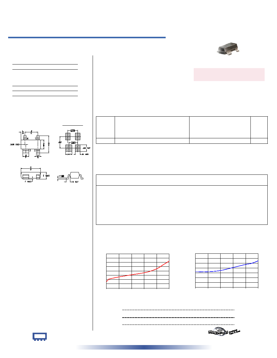
Typical Performance Data
Electrical Specifications at 25∞C
Maximum Ratings
Operating Temperature
-55∞C to 85∞C
Storage Temperature
-55∞C to 100∞C
Outline Drawing
Outline Dimensions ( )
LAT-10
ATTENUATION
10.0
10.1
10.2
10.3
10.4
10.5
10.6
10.7
10.8
0
500
1000
1500
2000
2500
FREQUENCY (MHz)
A
T
T
E
N
U
A
T
I
O
N
(
d
B
)
inch
mm
LAT-10+
LAT-10
50 0.5W 10dB DC to 2500 MHz
Fixed Attenuator
REV. D
M104321
LAT-10
060828
Miniature Surface Mount
LAT-10
VSWR
1.00
1.04
1.08
1.12
1.16
1.20
1.24
1.28
0
500
1000
1500
2000
2500
FREQUENCY (MHz)
VSWR
Features
∑ wideband, DC to 2500 MHz
∑ excellent VSWR, through entire band
∑ miniature size, SOT143 package
∑ aqueous washable
Applications
∑ cellular
∑ PCS
∑ ISM
∑ VHF/UHF
FREQ.
RANGE
(MHz)
ATTENUATION
(dB)
Flatness, Max.
VSWR
(:1)
Max.
MAX.
INPUT
POWER
1
(W)
DC-0.5
DC-1
DC-2.5
DC-0.5
DC-1
DC-2.5
f
L-
-f
U
Nom.
GHz
GHz
GHz
GHz
GHz
GHz
DC-2500
10±0.5
0.3
0.5
0.8
1.3
1.4
1.5
0.5
CASE STYLE: MMM168
PRICE: $1.95 ea. QTY (10-49)
+ RoHS compliant in accordance
with EU Directive (2002/95/EC)
The +Suffix identifies RoHS Compliance. See our web site
for RoHS Compliance methodologies and qualifications.
INPUT
4
OUTPUT
2
GROUND
1,3
Pin Connections
1. RF power at 25∞C case temperature: ΩWatt. Derate linearly to 0.2 Watt at 85∞C.
2. Flatness= variation over band divided by 2
Frequency
(MHz)
Attenuation
(dB)
VSWR
(:1)
designers kit available
Kit
No.
No. of Units
in Kit
Description
Price $
per Kit
K1-LAT
36
4 of ea. LAT-3(+), 6(+) ,10(+) ,15(+), 20(+)
2 of ea. LAT-1(+), 2(+), 4(+), 5(+), 7(+), 8(+), 9(+), 12(+)
59.95
A
B
C
D
E
F
G
H
J
K
.045
.055
.105
.120
.047
.005
.083
.104
.070
.080
1.14
1.40
2.67
3.05
1.19
0.13
2.11
2.64
1.78
2.03
L
M
N
P
Q
R
S
T
wt
.018
.24
.030
.036
.015
.021
.023
.005
grams
0.46
6.10
0.76
0.91
0.38
0.53
0.58
0.13
0.01
PCB Land Pattern
Suggested Layout,
Tolerance to be within
±.002
1.00
10.15
1.13
10.00
10.16
1.13
50.00
10.18
1.13
100.00
10.21
1.13
500.00
10.26
1.13
1000.00
10.31
1.14
1600.00
10.37
1.17
2000.00
10.45
1.19
2250.00
10.54
1.20
2500.00
10.63
1.22