A
B
C
D
E
F
G
.390
.31
.225
.060
--
.100
.045
9.91
7.87
5.72
1.52
--
2.54
1.14
H
J
K
L
M
wt
.420
.120
.060
.100
--
grams
10.67
3.05
1.52
2.54
--
0.50
LRPQ-700J
INSERTION LOSS
2.4
2.8
3.2
3.6
4.0
4.4
500
540
580
620
660
700
FREQUENCY (MHz)
INSERTION
LOSS
(dB)
S-1(dB)
S-2(dB)
INTERNET
http://www.minicircuits.com
P.O. Box 350166, Brooklyn, New York 11235-0003 (718) 934-4500 Fax (718) 332-4661
Distribution Centers NORTH AMERICA 800-654-7949 � 417-335-5935 � Fax 417-335-5945 � EUROPE 44-1252-832600 � Fax 44-1252-837010
Mini-Circuits
�
Mini-Circuits ISO 9001 & ISO 14001 Certified
Typical Performance Data
Splitter Electrical Specifications
Maximum Ratings
Pin Connections
SUMPORT
6
PORT 1 (0�)
4
PORT 2 (+90�)
1
GROUND
2,5
50 OHM TERM EXTERNAL
3
Operating Temperature
-40�C to 85�C
Storage Temperature
-55�C to 100�C
Power Input (as a splitter)
1W max.
LRPQ-700J
LRPQ-700J
2 Way-90� 50 500 to 700 MHz
Power Splitter/Combiner
REV. B
M105445
LRPQ-700J
HY/TD/CP
060818
Surface Mount
Features
� low insertion loss, 0.2 dB typ.
� excellent phase unbalance 1 deg. typ.
� aqueous washable
Applications
� modulators
� UHF
� signal proessing
� balanced amplifiers
� instrumentation
CASE STYLE: QQQ569
PRICE: $9.95 ea. QTY (1-9)
JRPQ-700J
ISOLATION
20
22
24
26
28
30
500
540
580
620
660
700
FREQUENCY (MHz)
ISOLATION (dB)
LRPQ-700J
PHASE UNBALANCE
89.0
89.2
89.4
89.6
89.8
90.0
500
540
580
620
660
700
FREQUENCY (MHz)
P
H
A
S
E
U
N
B
A
L
A
N
C
E
(
D
e
g
.
)
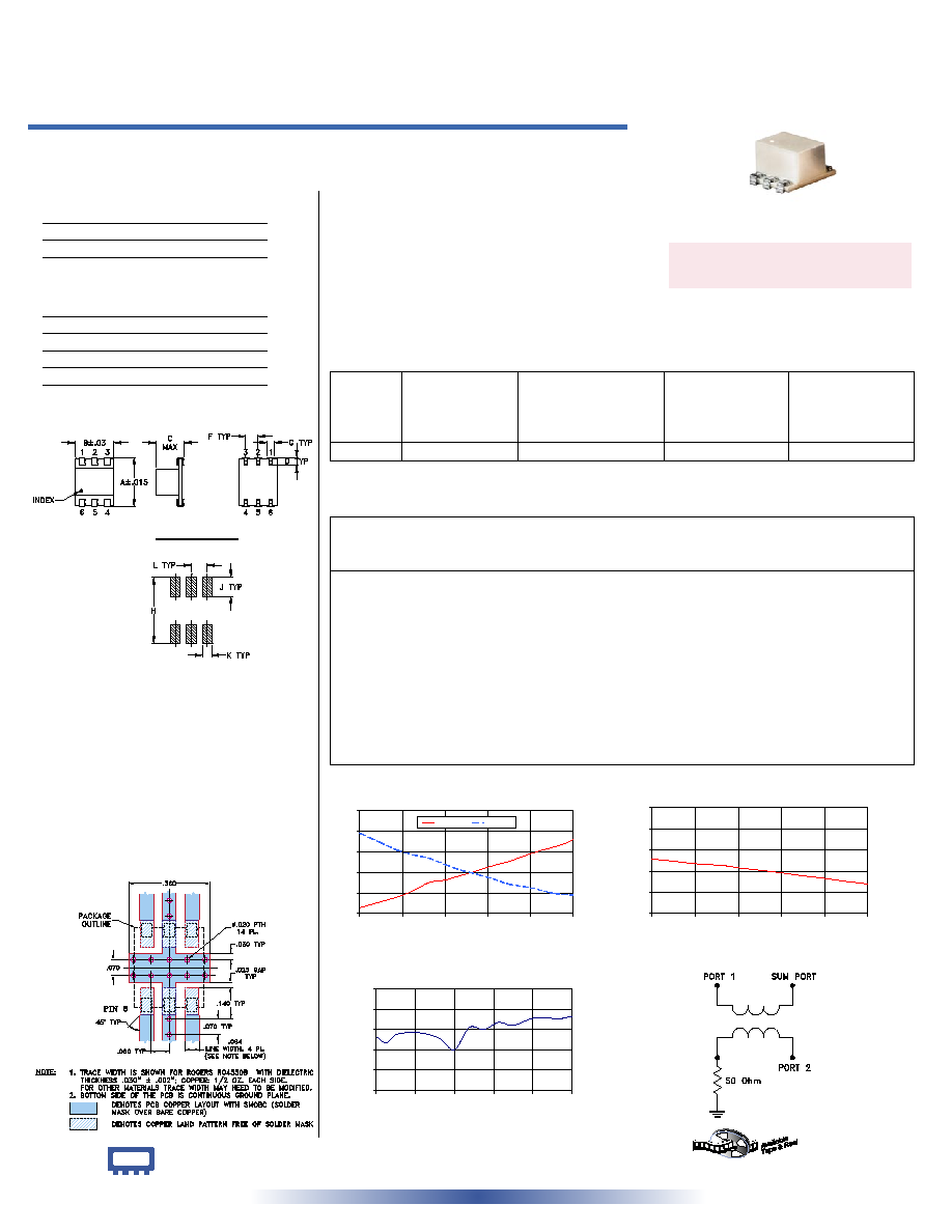
electrical schematic
Outline Drawing
Outline Dimensions ( )
inch
mm
PCB Land Pattern
Suggested Layout,
Tolerance to be within
�.002
Demo Board MCL P/N: TB-226
Suggested PCB Layout (PL-140)
Frequency
(MHz)
Insertion Loss
(dB)
Amplitude
Unbalance
(dB)
Isolation
(dB)
Phase
Unbalance
(deg.)
VSWR
S
VSWR
1
VSWR
2
S-1
S-2
LRPQ units have bottom barrier ground plane insulated with glass barrier.
+ RoHS compliant in accordance
with EU Directive (2002/95/EC)
The +Suffix identifies RoHS Compliance. See our web site
for RoHS Compliance methodologies and qualifications.
500.00
2.51
3.96
1.45
25.13
89.53
1.13
1.09
1.13
510.00
2.57
3.86
1.28
25.04
89.47
1.13
1.10
1.13
520.00
2.63
3.77
1.14
24.93
89.55
1.14
1.10
1.13
535.00
2.72
3.63
0.92
24.75
89.57
1.14
1.10
1.14
550.00
2.84
3.54
0.70
24.62
89.56
1.15
1.11
1.15
565.00
3.00
3.47
0.47
24.54
89.51
1.16
1.12
1.15
580.00
3.05
3.35
0.30
24.31
89.40
1.16
1.12
1.16
595.00
3.14
3.24
0.11
24.14
89.62
1.17
1.13
1.17
610.00
3.23
3.16
0.07
23.97
89.60
1.18
1.13
1.17
625.00
3.33
3.07
0.26
23.77
89.67
1.19
1.14
1.18
640.00
3.41
2.97
0.44
23.55
89.64
1.20
1.14
1.19
660.00
3.56
2.90
0.66
23.32
89.71
1.21
1.15
1.20
680.00
3.68
2.80
0.88
23.03
89.71
1.22
1.16
1.21
690.00
3.74
2.77
0.97
22.91
89.71
1.22
1.16
1.21
700.00
3.83
2.76
1.07
22.79
89.73
1.23
1.17
1.22
FREQ.
RANGE
(MHz)
ISOLATION
(dB)
INSERTION LOSS (dB)
Avg. of Coupled Outputs
less 3 dB
PHASE
UNBALANCE
(Degrees)
AMPLITUDE
UNBALANCE
(dB)
f
L
-f
U
Typ.
Min.
Typ.
Max.
Max.
Max.
500-700
23
18
0.2
0.6
3
1.8