A
B
C
D
E
F
G
.390
.31
.225
.060
--
.100
.045
9.91
7.87
5.72
1.52
--
2.54
1.14
H
J
K
L
M
wt
.420
.120
.060
.100
--
grams
10.67
3.05
1.52
2.54
--
0.50
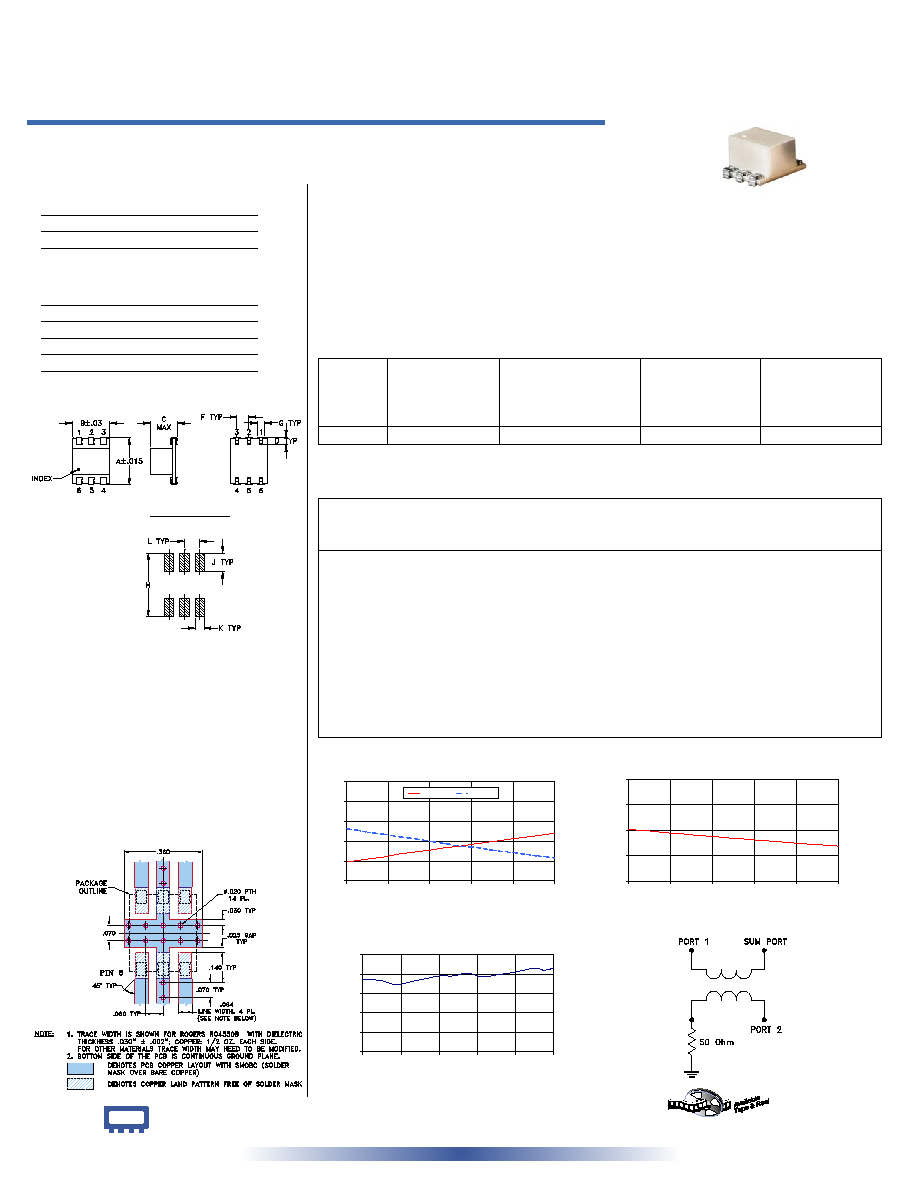
LRPQ-70J
INSERTION LOSS
2.4
2.8
3.2
3.6
4.0
4.4
65
67
69
71
73
75
FREQUENCY (MHz)
INSERTION
LOSS
(dB)
S-1(dB)
S-2(dB)
INTERNET
http://www.minicircuits.com
P.O. Box 350166, Brooklyn, New York 11235-0003 (718) 934-4500 Fax (718) 332-4661
Distribution Centers NORTH AMERICA 800-654-7949 � 417-335-5935 � Fax 417-335-5945 � EUROPE 44-1252-832600 � Fax 44-1252-837010
Mini-Circuits
�
Mini-Circuits ISO 9001 & ISO 14001 Certified
Typical Performance Data
Splitter Electrical Specifications
Maximum Ratings
Pin Connections
SUMPORT
6
PORT 1 (0�)
4
PORT 2 (+90�)
1
GROUND
2,5
50 OHM TERM EXTERNAL
3
Operating Temperature
-40�C to 85�C
Storage Temperature
-55�C to 100�C
Power Input (as a splitter)
1W max.
LRPQ-70J
2 Way-90� 50 65 to 75 MHz
Power Splitter/Combiner
REV. A
M102713
LRPQ-70J
HY/TD/CP
060818
Surface Mount
Features
� low insertion loss, 0.1 dB typ.
� high isolation, 30 dB typ.
� excellent phase unbalance 1 deg. typ.
� excellent return loss, VSWR 1.12:1 typ.
� aqueous washable
Applications
� VHF
� instrumentation
� modulators
� balanced amplifiers
CASE STYLE: QQQ569
PRICE: $9.95 ea. QTY (1-9)
LRPQ-70J
ISOLATION
25
27
29
31
33
65
67
69
71
73
75
FREQUENCY (MHz)
ISOLATION (dB)
LRPQ-70J
PHASE UNBALANCE
90.0
90.2
90.4
90.6
90.8
91.0
65
67
69
71
73
75
FREQUENCY (MHz)
P
H
A
S
E
U
N
B
A
L
A
N
C
E
(
D
e
g
.
)
electrical schematic
Outline Drawing
Outline Dimensions ( )
inch
mm
PCB Land Pattern
Suggested Layout,
Tolerance to be within
�.002
Demo Board MCL P/N: TB-226
Suggested PCB Layout (PL-140)
Frequency
(MHz)
Insertion Loss
(dB)
Amplitude
Unbalance
(dB)
Isolation
(dB)
Phase
Unbalance
(deg.)
VSWR
S
VSWR
1
VSWR
2
S-1
S-2
LRPQ units have bottom barrier ground plane insulated with glass barrier.
65.00
2.78
3.45
0.68
29.08
90.74
1.12
1.11
1.06
65.50
2.81
3.42
0.61
29.00
90.74
1.12
1.11
1.06
66.00
2.84
3.38
0.54
28.95
90.73
1.12
1.11
1.06
66.75
2.88
3.34
0.45
28.81
90.69
1.12
1.11
1.06
67.50
2.94
3.29
0.35
28.73
90.72
1.12
1.11
1.06
68.25
2.98
3.25
0.27
28.60
90.75
1.12
1.11
1.06
69.00
3.02
3.20
0.18
28.52
90.78
1.12
1.11
1.06
69.75
3.07
3.15
0.09
28.40
90.78
1.12
1.11
1.06
70.50
3.10
3.10
0.00
28.32
90.81
1.12
1.11
1.06
71.25
3.15
3.07
0.08
28.21
90.77
1.12
1.11
1.06
72.00
3.19
3.02
0.17
28.13
90.79
1.12
1.11
1.06
73.00
3.25
2.97
0.29
27.99
90.82
1.12
1.11
1.06
74.00
3.30
2.91
0.39
27.87
90.86
1.12
1.11
1.06
74.50
3.33
2.89
0.45
27.83
90.84
1.12
1.11
1.06
75.00
3.36
2.86
0.50
27.76
90.86
1.12
1.11
1.06
FREQ.
RANGE
(MHz)
ISOLATION
(dB)
INSERTION LOSS (dB)
Avg. of Coupled Outputs
less 3 dB
PHASE
UNBALANCE
(Degrees)
AMPLITUDE
UNBALANCE
(dB)
f
L
-f
U
Typ.
Min.
Typ.
Max.
Max.
Max.
65-75
30
20
0.1
0.5
3
1.0